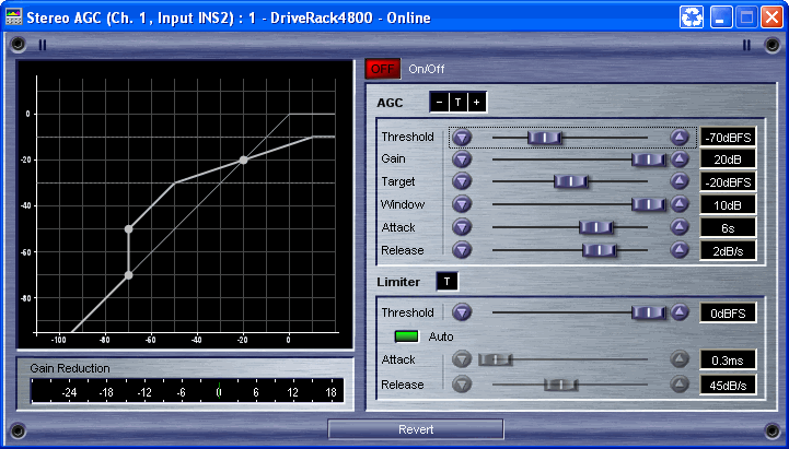
![]() Automatic Gain Control - The AGC is used to keep the average level of a signal at a constant level. High level signals are reduced by a fast limiter to prevent distortion by clipping. The AGC Threshold meters show what region of the AGC the input signal is in, T (yellow) within the Window, A + (red) Limiter, A - (green) adding Gain.
Automatic Gain Control - The AGC is used to keep the average level of a signal at a constant level. High level signals are reduced by a fast limiter to prevent distortion by clipping. The AGC Threshold meters show what region of the AGC the input signal is in, T (yellow) within the Window, A + (red) Limiter, A - (green) adding Gain.
![]() All changes are made in real time. If you wish to keep changes made, close the control panel with the "X" in the upper right hand corner. If you do not want to keep the changes, click the "revert" button and all values will return to their original value (when the panel was opened). Once you have closed the panel, you cannot undo or revert changes.
All changes are made in real time. If you wish to keep changes made, close the control panel with the "X" in the upper right hand corner. If you do not want to keep the changes, click the "revert" button and all values will return to their original value (when the panel was opened). Once you have closed the panel, you cannot undo or revert changes.

On/Off button - The On/Off button turns the Auto Gain Control on and off; when in the Off position, the signal path bypasses this algorithm.
Threshold fader - This fader changes the level at which the AGC recognizes a signal as a legitimate level to be increased into the AGC level window. The Threshold also defines the lower limit of the AGC. This prevents the AGC from adding gain to low level signals or noise.
Gain fader - This is the maximum amount of gain to be applied to the signal after it crosses the threshold limit in an attempt to reach the target.
Target fader - This is the user defined optimum signal level to be achieved and maintained.
Window fader - This fader adjusts the size of the window around the target. Decreasing the size of the window maintains tighter control of the signal, while opening the window up provides less control.
Attack fader - This fader sets the length of time that gain or gain reduction will be applied after a signal crosses the threshold.
Release fader - This fader determines the rate of change that will take effect after the signal level has fallen below the threshold, and will no longer be controlled by algorithm.
Limiter Threshold fader - This is the final word on output level. If the signal level reaches the limit threshold, the gain will be reduced with an 8:1 ratio.
Auto button on/off - Auto mode dynamically sets the Limiter Attack and Release parameters based on the input signal. This button turns on the automatic Attack and Release function for the limiter section of the AGC.
Limiter Attack fader - This fader defines the time after signal has crossed the threshold that the limiter will start attenuating the output signal level.
Limiter Release fader - This fader defines the rate of limiting release. Once the input signal falls below the threshold the limiter will stop attenuating at this rate.
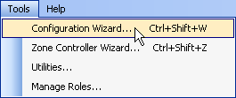
Configuration - To configure this section, select Tools from the Menu Bar. Then select Configuration Wizard.

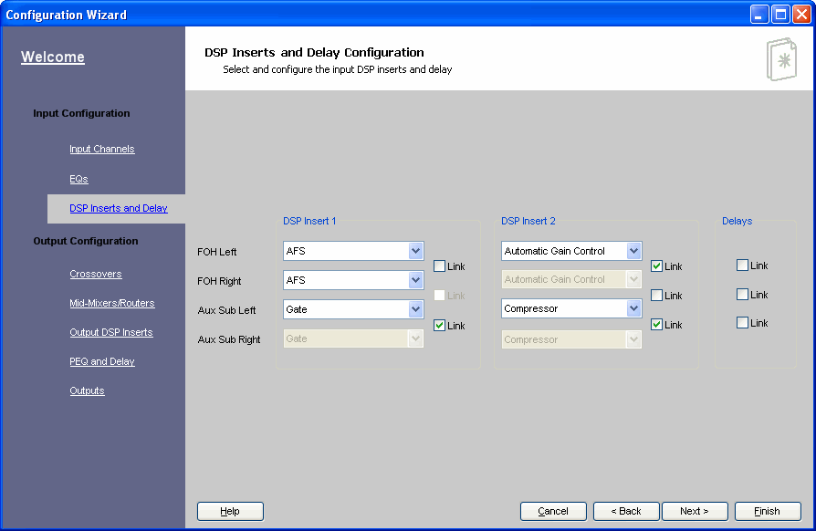
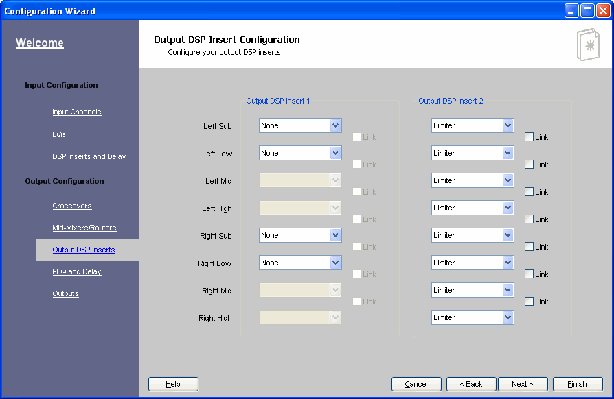
Click on the DSP Inserts and Delays link, or the Output DSP Inserts link.

