The Soundweb London BLU-102 offers a fixed configuration of 10 analog inputs and 8 analog outputs, an analog telephone interface, configurable signal processing, AEC processing, and a high bandwidth, fault tolerant digital audio bus. The RJ-11 port enables the BLU-102 to interface with a standard POTS (aka PSTN or Analog PBX) telephone network. The BLU-102 has open architecture which is fully configurable through HiQnet™ Audio Architect. A rich palette of processing and logic objects and a “drag and drop” method of configuration provide a simple and familiar design environment.
The BLU-102 contains dedicated AEC processing for up to 8 independent AEC algorithms. The AEC algorithm can be applied to signals coming from the local analog inputs or
from the digital audio bus. 8 individual AEC references (one per algorithm) allow the user to provide a solution for multiple conferencing spaces using a single device.
Automatic Gain Control (AGC) and Noise Cancellation (NC) are also provided per AEC algorithm. AGC ensures that microphone levels remain at an optimum level, and NC removes steady state noise (such as from a projector fan or air conditioning device) from the signal path. This processor features a low latency, fault tolerant digital audio bus of 48 channels which uses standard Category 5e cabling giving a distance of 100m between compatible devices. Fiber media converters can be used to increase the distance between devices to over 40km.
The BLU-102 is compatible with the entire Soundweb London family and its 48 channel digital audio bus represents channels 1-48 of the larger 256 channel digital audio bus when integrated with the BLU-800, BLU-320, BLU-160, BLU-120, BLU-BIB and BLU-BOB devices.
Analog Inputs provide software configurable gain in 6dB steps up to +48dB per channel and software selectable Phantom Power per channel. Phantom Power, Signal Present and Clip information per channel is easily accessible, without the requirement for a PC, from clear front panel LED indication. A bi-directional locate function allows devices to be identified both from and within HiQnet Audio Architect. 12 Control Inputs and 6 Logic Outputs allow the BLU-102 to be integrated with GPIO compatible devices.
Name: The name of this item
Class Name: The type of this device
Device ID: The ID number of this device
Acknowledge (ACK): Set to 'yes' to inform the London device that is should expect acknowledgement of the messages being sent.
Baud Rate: Drop-down selection for the Baud Rate
Data Bits: The number of bits for data
Parity: The parity
Stop Bits: The number of stop bits
Dynamic Meters: The number of Dynamic Meters to use in this device. Hover the cursor over a wire in the design while online and a Dynamic Meter displays the signal level.
Logic Change Block: If enabled, only Logic Sources and Ends will be written to the change block. Only enable if there are performance issues with logic.
Logic Subscription: If enabled, only Logic Sources and Ends will be subscribed to. Only enable if there are issues with logic.
Recall Presets on Startup: When enabled, presets assigned to control ports will be recalled when the device is powered on.
Control Port Subscribe: When enabled, force control ports to subscribe to controlled parameters.
Sample Rate Pulldown: Sample rate pulldown frequency when an external sync source is being used

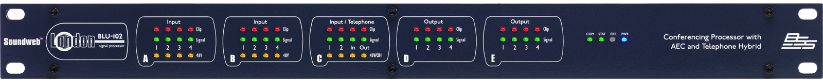
Each channel has the following LED indicators:
Clip:Indicates clipping in the analog domain for each Input or output channel. The LED will illuminate at +18.5dB.
Signal: The Signal LED will illuminate for each Input or output channel when the signal reaches or exceeds the signal threshold of -20dB. Input channels have a third indicator:
(Input channel only) Illuminates to indicate +48V phantom power has been activated for the relevant input channel.
OH: Indicates when the telephone hybrid is off-hook
IN: Illuminates green when the telephone hybrid is receiving signal (RX)
OUT: Illuminates green when the telephone hybrid is transmitting signal (TX)
OTHER INDICATORS
Each Soundweb London has indicators on the front panel to display the following:
The COM LED indicates the presence and status of an Ethernet network connection.
OFF - Indicates that no Cat 5 Ethernet cable is present, or that the unit is still in the process of negotiating its IP address.
GREEN - Indicates that a Cat 5 Ethernet cable is present and that the unit has established its IP address.
YELLOW - will flash Yellow to indicate that the device is communicating with another control device, either on the network, serial or control ports.
The STAT LED will illuminate :
GREEN when a proper design file is loaded and running
YELLOW if the design is paused
RED if design is stopped.
ERR: The ERR LED will normally be off. It will illuminate RED in the case of a critical or fatal error.
PWR: The PWR LED will be illuminated BLUE to indicate that the unit is powered up. When the unit is 'located', this LED will blink.
| MODE | DESCRIPTION | COM/STAT/ERR Indication |
|
Error |
This indicates an error during the boot sequence. (for example, no valid application is present) |
Solid RED colour |
|
BootLoader Mode |
The unit is in 'bootloader' mode, either briefly during the normal startup process, or stopped in this mode for firmware maintenance purposes | Solid YELLOW colour |
|
Welcome screen |
During normal startup process. |
Solid GREEN colour |
|
Startup Mode |
The unit is starting up. At this point the user can put the unit into ‘safe mode’ by pressing and holding the rear locate button |
Chasing YELLOW pattern |
|
Firmware Update Mode |
The unit is undergoing a firmware upgrade, flash is being erased or programmed |
Chasing GREEN pattern |
AC Mains input to the universal switched-mode power supply, operates over a wide range of AC input voltages from 100V to 240V, 50/60Hz.
Pressing the Locate switch on the rear of the unit will illuminate the PWR LED on the front and identify the device within Audio Architect. Similarly the switch and PWR LED will illuminate if the device is located from within the application.
Serial port for connection of external control equipment.
The London BLU link is a point-to-point digital audio bus with 256 audio channels at 48K sample rate or 128 audio channels at 96K sample rate. The BLU-102 allows access to channels 1-48 of this bus at 48kHz and 47.952kHz (Pulldown) sample rates. The physical connection is made with Cat 5e cable from the OUT port of one device to the IN port of another device. The devices are connected in a daisy chain fashion continuing with the OUT port of one device connected to the IN port of the next device. Redundancy can be provided by completing the loop and connecting the OUT port from the last device to the IN port of the first device in the chain. All devices connected in the London BLU link chain must be configured for the same audio sample rate.
There are 12 analogue input connections and 8 analogue output connections. The analogue connections are balanced, on Phoenix/Combicon connectors.
AEC
The BLU-102 has AEC capabilities which enable it to cancel acoustic echo arising when sound from a loudspeaker enters a microphone in the same room in a conference application.
The BLU-102 contains dedicated AEC processing for up to 12 independent AEC algorithms. The AEC algorithm can be applied to signals coming from the local analog inputs or from the digital audio bus. 12 individual AEC references (one per algorithm) allow the user to provide a solution for multiple conferencing spaces using a single device. Automatic Gain Control (AGC) and Noise Cancellation (NC) are also provided per AEC algorithm. AGC ensures that microphone levels remain at an optimum level, and NC removes steady state noise (such as from a projector fan or air conditioning device) from the signal path. Non-Linear Processing (NLP) dynamically adjusts to minimize echo caused by under or over-cancellation.
Telephone Jack
The BLU-102 has a telephone hybrid in and out channel via a telephone jack. This RJ-11 jack allows connection to a standard POTS (aka PSTN or Analog PBX) telephone network.
All audio and control connections to the BLU-102 are via Klippon pluggable terminal block connectors (also known as BL, Phoenix or Combicon). 12-way female Klippon connectors are supplied for making these connections.
Soundweb products provide cable shielding ’back from the destination’ to eliminate ground loop problems. This means that the shield (S) connection on an input is grounded, whereas the shield connection on an output is floating (although connected via an internal network to ground for EMC compliance).
Balanced wiring - The convention for balanced wiring (2-core plus shield) is:
Unbalanced wiring - The convention for unbalanced wiring to the inputs (1-core plus shield) is:

Used to connect switches or potentiometers, e.g. BLU-3 selector wallplate (Part no. Z-BLU-3). Looking at the control port connector (on the back of the unit), there are two common (ground) connections C to the left of the eight CONTROL INPUTS and, two software assignable reference voltage outputs R to the right. The control ports now have two modes of operation. In Soundweb Designer’s Control Ports window these are labelled ’2-wire’ and ’3-wire’. See more information on Wiring Modes here.
See information on the Logic Outputs HERE.
|
Mains Voltage |
100-240V AC, 50/60Hz |
|
Power Consumption |
<55VA |
|
BTU Rating |
<188 BTU/hr |
|
Operating Temperature Range |
5 to 35 °C (41 to 95 °F) |
|
Dimensions (HxWxD) |
1.75" (45mm) (1U) x 19" (483mm) x 9" (318mm) |
|
Weight |
6.4lbs / 2.9kg |
|
Per Analogue or AEC Input |
Signal Present, Clip, 48V |
|
Telephone Hybrid |
Tx, Rx, OH |
|
Other |
COM, STAT, ERR, PWR |
10 electronically balanced on Phoenix/Combicon removable screw connectors.
|
Mic/Line Inputs |
Nominal gain 0dB, electronically switchable up to +48dB, in +6dB steps |
|
Input Impedance |
3.0kOhms |
|
Maximum input level |
+20dBu with 0dB input gain, +8dBu with 12dB gain |
|
CMRR |
>75dB at 1 kHz |
|
Equivalent Input Noise (E.I.N.) |
<-125dBu typical with 150 Ohm source |
|
Phantom power |
48V nominal, selectable per input |
|
A/D Latency |
37/Fs (0.77ms @ 48k) |
8 Independent Algorithms
|
AEC Processing Latency (Original AEC) |
2385/Fs [49.69ms @ 48kHz] |
|
AEC Processing Latency (Full Bandwidth AEC) |
1584/Fs [33ms @ 48kHz] |
|
Tail Length |
200ms |
|
Average Convergence Rate |
49dB/s (Net convergence over multiple FFT bands) |
|
|
|
RJ-11 Connector
|
AC-REN |
0.0B |
|
Dynamic Range |
67dB |
|
Frequency Response |
300 to 3.3kHz |
|
THD |
<0.3% |
|
Transhybrid Loss |
>48dB with LEC enabled |
|
LEC Tail Time |
64ms |
|
TX Level |
-10dBm RMS average |
|
RX Level |
+3.2dBm RMS |
8 electronically balanced on Phoenix/Combicon removable screw connectors
|
Maximum Output Level |
+19dBu |
|
Frequency Response |
20Hz-20KHz (+0.5dB/-1dB) |
|
THD |
<0.01% (20Hz to 20kHz, +10dBu output |
|
Dynamic Range |
>108dB typical (22Hz to22kHz unweighted) |
|
Crosstalk |
<-75dB |
|
D/A Latency |
29/Fs (0.60ms @ 48k) |
|
Output Impedance |
40 Ohms balanced and 20 Ohms unbalanced |
12 inputs and 6 outputs
|
Control Input Voltage |
0 to 4.5v |
|
Control Input Impedance |
4.7kOhms to +5V (2-wire mode), >1MOhm (3-wire mode) |
|
Logic Output Voltage |
0 or +5V unloaded |
|
Logic Output Impedance |
440 Ohms |
|
Logic Output Current |
10mA source, 60mA sink |
Phoenix/Combicon connector for failsafe control
|
Opto Output Current |
14mA maximum |
|
Withstanding Voltage |
80V maximum (Off) |
|
Series Impedance |
220 Ohms (Isolated) |