The BLU-103 has two VoIP in/out(TX/RX) channels via a VoIP jack. This RJ-45 jack allows connection to a standard VoIP network.
The BLU 103 VoIP interface allows making and receiving phone calls over any Voice_over-IP (VoIP) system that adheres to the SIP (Session Initiation Protocol) standard. ‘Card’ position C is used to accommodate two VoIP (SIP v2.0 or later) lines which allows 2 mono VoIP calls concurrently.
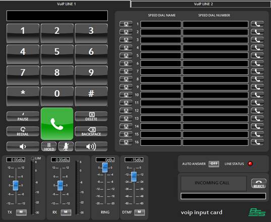
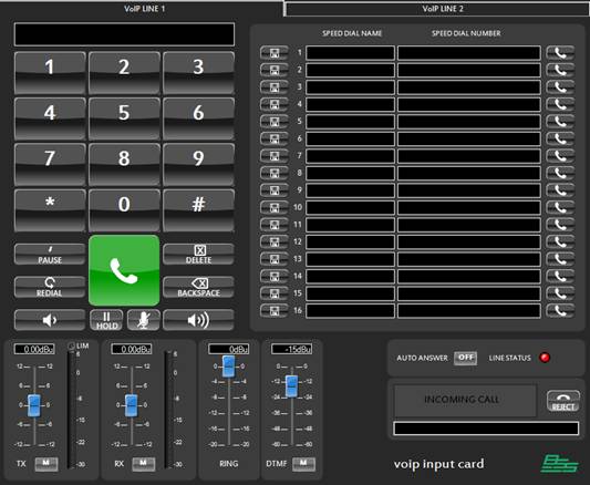
The VoIP control panel in HiQnet Audio Architect™ contains two pages of controls for Line 1 and Line 2 respectively.
VoIP controls:
Telephone keypad
Audio level controls
Speed Dial
Auto Answer
Call Status
16 speed-dial numbers.
Reject call
Caller ID
Telephone number edit: This edit control displays the current telephone number being entered via the keypad button.
Keys 0-9, * and #: The buttons add a character to the number that is being entered in the telephone edit. If these buttons are pressed during a call then a DTMF tone is played.
Pause: This key adds a comma to the current telephone number. When dialed the comma causes the dialer to pause for 3 seconds before dialing the next number.
Delete: Deletes the complete telephone number from the Telephone number edit
Backspace: Removes the last character from the current telephone number. This allows the number to be corrected if the wrong button has been pressed.
Redial: Re-dials the last dialed number.
Pick Up/Hang Up: The large green/red button with a telephone icon is the "Pick Up/Hang Up" button. It is used to take the VoIP line off hook and then place it back on hook again While on hook, dial the number to call and then press the "Pick Up/Hang Up" button to take the VoIP line off hook. When the call is over, hit the "Pick Up/Hang Up" button again to place the VoIP line back on hook.
Hold: Puts the active call on Hold
Reject Call: Press to reject an incoming call at the near end
Caller ID: Displays the caller ID information
Volume Up/Down: Adjusts the level of the received audio (far-end) of the VoIP interface.
Mute: Mutes the transmitted audio. When muted the far end cannot hear near end audio.
TX Level: Controls the level of the transmitted audio.
TX Mute: Mutes the transmitted audio.
RX Level: Controls the level of the received audio.
RX Mute: Mutes the received audio.
RX Meter: Meters the received audio.
It is possible to store up to 16 different speed dial numbers directly from the control panel. Each of these numbers can be stored and recalled using just the buttons on the control panel. Alternatively, the speed dial numbers can be edited directly using the 'Speed Dial Number' edit controls.
To store a speed dial there are two methods.
Edit the number in the 'Speed Dial Number' edit directly
Enter a number in the current telephone number edit using the dial buttons. Once the number has been entered press the 'store' button for the speed dial you want to store the number into.
A name can be entered for the speed dial numbers in the 'Speed Dial Name' edit box.
A further 34 (50 in total) speed dials can be accessed from the design tree by dragging onto a phone number edit control on a custom control panel.
To recall a speed dial simply press the 'dial' button next to the required speed dial number. This will automatically dial the number.
DTMF Level: Controls the level of the DTMF tones generated when dialing a number. This fader only adjusts the DTMF level heard by the near-side. This allows the user to balance the DTMF signal component of the reinforced signal mix.
Ring tone Level: The ringtone is the audio sample that is played when an incoming call is detected. The level of the ringtone can be adjusted.
Auto-Answer: Set this to ON for the VoIP card to automatically answer a call or after a fixed number of rings.
The number of rings is set from Auto Answer Ring Count under VoIP PO properties – Line Tones.
Line Status:
Line status indicates the status of Line 1 and Line 2. This depends on line 1 and line 2 Account Status property under VoIP PO panel properties.
Line Status indicates Red withAccount Status as Proxy Registered
Line Status indicates Green with Account Status as Not Configured/Registration Failure.
Refer to the Account Status section under VoIP PO properties for further information.
VoIP Card Properties
Configuring a VoIP line for establishing a call is accomplished by setting VoIP PO line properties. These properties should be set independently for Line 1 and Line 2.
The properties are categorized as below:
· Tones
· Protocol
· Timers
· NAT
Network
VoIP Network:
Set the VoIP network properties to configure the BLU-103 VoIP card to a VoIP exchange network.
Connection Type
· DHCP – The VoIP card IP is be set from a DHCP server or auto IP. The settings include IP address, Subnet mask, Gateway and DNS. These fields will not be populated until Audio Architect is online to a device which has a successful connection to a VoIP exchange.
· Static – The fields will be enabled to allow the IP settings to be entered manually.
VLAN Enabled
Check the VLAN enabled checkbox if using a tagged VLAN. This will enable the VLAN ID and VLAN Priority fields for the relevant values to be entered.
If the network uses an untagged VLAN or no VLAN, leave this box unchecked.
Ethernet Status
This field is populated once Audio Architect is online to a device and will indicate one of three states:
· Disconnected – there is no connection to the VoIP exchange.
· Connected – connection to the VoIP exchange has been successful.
· Connecting – there has been a connection failure
The fields IP Address, Subnet Mask, DNS, Gateway, MAC Address and Ethernet speed are reflected after going online with BLU-103, only when there is successful connection with the VoIP network.
STUN Port
Enter the STUN server port number here. This is usually 3478
STUN Server
Enter the STUN server IP address here
VoIP Network Time
VoIP Network Time specifies the settings to enable the device’s clock synchronization with the NTP server periodically.
NTP
NTP is widely-used to synchronize system clocks among a set of distributed time servers and clients. Once online the Synchronized Date and Synchronized Time fields will be populated using NTP protocol.
Synchronized Date and Time
These fields are populated when online to the BLU-103. The time is set using the NTP protocol.
NTP Enabled
By default NTP is enabled. An active internet connection is required
Daylight Saving Time
Check this box for daylight saving
Time Zone
Adjust the Time Zone based on your region.
NTP Server
This field is populated with a default NTP server address. An active internet connection is required.
Time Synchronization Interval
Select the periodic time interval for synchronization to the NTP server.
Ring Type
Ring type can be selected as classic or silent
DTMF mode
Within a VoIP conversation, DMTF tones are delivered either in-band (as a beep), or out-of-band via SIP or RTP signaling messages.
· None - Disable DTMF support for both Tx and Rx
· In-Band - Incoming stream delivers DTMF signals in-audio independently of codecs – VoIP processor listens to the audio stream, and will detect/extract the DTMF signals.
· Out-Of-Band - Incoming stream delivers DTMF signals out-of-audio using RFC-2833 mechanism, independently of codecs – in this case the DTMF signals are sent separately from the actual audio stream
· SIP_Info - This mode uses Out-of-Band signaling using SIP packets
Note: SIP-INFO is not recommended for DTMF delivery, since it cannot deliver strokes synchronously with the audio stream, introducing timing artifacts.
DTMF On Time (ms)
Sets the length of time at which DTMF tones will be generated. This is more applicable when DTMF mode is selected as ‘in-band’. All other times, this is the length of time that the DTMF feedback tone is heard back on the speaker.
DTMF Off Time (ms)
Sets the length of the pause between DTMF tones.
Auto Answer Ring Count
This property is used to automatically answer an incoming call either immediately or after a set number of rings. The Auto Answer control on the VoIP control panel must be set to ON for this setting to have any effect.
Ring count options that can be set:
Immediately, 1 Ring, 2 Rings and 3 Rings
DTMF Tone Mute
When this box is checked the DTMF tone is not generated whenever a key on dial pad is pressed.
DTMF fixed length
Selecting fixed length, means DTMF tone’s ON time is fixed to 160ms. DTMF On/Off time control settings are not applicable in this case.
With fixed length not selected, Set the DTMF on and off times. Minimum on/off time is 50ms and maximum is 1000ms.
Line Protocols
Configuring the Line protocol properties enables the registering of VoIP lines to the VoIP server.
User Name
The VoIP extension assigned to your VoIP line when signed up for VoIP service.
Authentication Name
Normally user name is sufficient to authenticate VoIP account with server. If user name and authentication name are different, specify authentication name here.
Password
Password to authenticate the VoIP account with the server
Display name
This will be presented as your Caller ID to the remote party.
Domain Name
IP Address or domain name of the VoIP server
Account Status
Account Status displays the VoIP line’s registration status.
· PROXY REGISTEREDwith successful registration
· REGISTRATION FAILUREwith incorrect User Name/Password
The other status messages that are displayed as Account Status are
NOT CONFIGURED
When one of the basic fields for account configuration is missing (user name, password, domain name, authentication name etc)
CONFIGURING, CONFIGURING, REGISTERING
Intermediate states before successful registration.
P2P_REGISTERED
Point to Point Registered.
PROTOCOL_ERROR
The transport may have been lost. This usually happens if the transport connection with the server goes down and must be re-established.
PROXY_TIMEOUT
There was a Account Creation failure during any of the below conditions
1. During account creation, the network may have failed to be set up. This includes the inability to resolve the server’s location, creating a SIP transport with the server, etc.
2. During account creation, SIP may have failed to load the account information from the Info Subsystem
STUN Enabled
By default is STUN is disabled.
Register with Domain
Enabled by default.
Registration Life(s)
Registration Life determines the interval during which the VoIP line will attempt to re-register with the server. Note that the proxy may override this setting with a value of its own. If an acknowledgement has not been received from the Proxy within the agreed time the VoIP card registration information kept in the proxy's database will be cleared. The default registration expiration period is 3600 seconds and should be left at this value unless specified by the network administrator. Can be set between 60 to 86400 seconds.
Registration Retry(s)
Registration Retry determines the interval in seconds after which VoIP card tries to re- register when there is a registration failure.
Proxy Address
The proxy address for accessing VoIP service
Proxy Port
The network port of the VoIP Phone that is used to communicate with the proxy server.
Default proxy port is 5060 in VoIP systems, but this number can be modified if needed. Value ‘0’ for port indicates any port can be used.
Signaling Port
The signaling Port is used to direct incoming SIP traffic to the correct Line for communications between the VoIP card and the Proxy. The default port for Line 1 is 5060 and the default port for Line 2 is 5062. These settings should be left at this value unless specified by the network administrator.
SRTP Preference
Secure Real-time Transport Protocol, enables secure communication using SRTP media encryption. Available if Transport is set to TCP or TLS. SRTP can be set to Disabled, Allowed, Preferred or Required.
Transport
This is the SIP protocol transport mode and can be set to Auto, TCP or TLS.
By Default it is set to Auto which uses UDP.
RPort Enabled
RPort Enabledchanges the default port that RTP is using. The port number ranges from 8000 (default) to 8100.
RTP Port Start
The first RTP Port used by this line. Must be between 4000 - 65534 and must be one less than the RTP Port End.
RTP Port End
The last RTP port used by this line. Must be between 4001 - 65535 and must be one more than the RTP Port Start.
Line Timers
Do not change these settings unless well aware of its consequences. Contact network administrator before changing settings in this TAB.
Session Timer
Enables periodic refresh of SIP sessions through a Re-INVITE or UPDATE request. When disabled the Default Session Timer, Minimum Session Timer, Maximum Session Timer options will be disregarded. If a call unexpectedly disconnects, disabling this option may help.
Minimum Session Timer
If the proxy tries to override the Maximum Session Timer value as specified in the VoIP card, the time entered in this field will be the minimum value allowed. Can be set between 90 to 65535 seconds, default = 90.
Maximum Session Timer
Determines the interval during which the VoIP card will try to negotiate with the Proxy to keep the VoIP session alive. Note that the proxy may override this setting with a value of its own. If a Session Refresh request is not properly received by both parties within this agreed time, the session will expire and the call will end. This can be set between 90 and 65535 seconds, the default is 1800 and this value should be used unless specified otherwise by the network administrator.
Transaction Timer Auto Adapt
When enabled, the FCM SIP implementation attempts to automatically adjust the values of the SIP transaction timers in order to compensate for adverse network conditions. This can decrease unnecessary message retransmissions and failures on slow or inconsistent networks like cellular data. The adjustments are based on the round-trip times of OPTIONS requests sent purely for the purpose of measurement as well as on the round-trip times of normal REGISTER requests.
Transaction Timer Auto Adapt Interval
Specifies the interval in seconds at which the network round-trip time is measured when automatic adaptation of transaction timers is enabled. Default is 60 secs.
Retransmit Timeout
The total amount of time the card will continue to retransmit a UDP packet that has not been responded to.
Line Timers
The T1, T2, and T3 settings will be overridden if automatic adaptation of transaction timers is enabled. It is recommended not to change this value.
Attribute |
Default |
Description |
500 |
(optional) Specifies the duration of the SIP timer T1 (round trip time estimate) in milliseconds. For unreliable transports, such as UDP, the client transaction retransmits requests at an interval that starts at T1 seconds and doubles after every retransmission. T1 is an estimate of the round-trip time (RTT). Nearly all of the SIP transaction timers scale with T1, and changing T1 adjusts their values. |
|
4000 |
(optional) Specifies the duration of the SIP timer T2 (maximum retransmit interval for non-INVITE requests and INVITE responses) in milliseconds. For unreliable transports, requests are retransmitted at an interval which starts at T1 and doubles until it reaches T2. If a provisional response is received, retransmissions continue for unreliable transports, but at an interval of T2. T2 represents the amount of time a non-INVITE server transaction takes to respond to a request if it does not respond immediately. |
|
5000 |
(optional) Specifies the duration of the SIP timer T4 in milliseconds. T4 represents the amount of time the network takes to clear messages between client and server transactions. |
Line NAT
Keepalive
When enabled, Keepalive causes messages to be sent to the SIP server periodically for the sole purpose of keeping a NAT pinhole open.
Keepaalive Mode
When keepalive functionality is enabled, Keepalive Mode determines the mechanism that will be used to perform the keepalive. Can be set to SIP or Register.
Keep-alive interval
When keepalive functionality is enabled, this value determines the interval, in seconds, between keepalive messages. The interval can be set from 20s to 30s; the default is 20s.
TCP keep alive
When Enabled, TCP keepalive functionality causes TCP messages to be sent to the SIP server periodically for the sole purpose of keeping a NAT pinhole open. This is preferred over the standard SIP keep-alive when the application may sleep as the OS sends the TCP keep-alive.
TCP Keepalive interval
When TCP keepalive functionality is enabled, this value determines the interval, in seconds, between two successive TCP keepalive messages.
Audio Architect Configuration Symbol
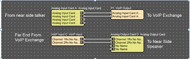
VoIP Interface configuration symbols in HiQnet Audio Architect Default Configuration view:
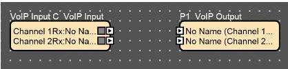
The left hand VoIP block has 2 channels for input from the VoIP exchange to be processed by the VoIP card. The right hand block returns audio to the exchange.
Connecting the VoIP Card
In a teleconferencing system the VoIP card would be connected as shown below:
1. Under the “VoIP Network” in the Properties select “DHCP”.
2. In the same tab, check the “VLAN Enabled” checkbox
3. Under properties go to “Line 1 Protocol” tab
· Enter the user name, authentication name
· Enter the password
· Enter the Display name
· Enter VoIP server address i.e., cisco call manager’s address in the “domain name” field.
· STUN and SRTP are disabled by default
· Transport set to Auto
4. To register Line 2 go to “Line 2 Protocol” and repeat the above steps
5. Go online to Audio Architect
6. The “Account Status” will display “Proxy Registered” once the registration is successful
7. If the registration is unsuccessful it will displayed as “Not configured”, “AUTHENTICATION_FAILURE”.
Placing a call from Audio Architect is performed only if the user is registered to the network [Check the “account status” field]. Once registered, follow the below steps to make a call.
1. Open up the VoIP PO default panel
2. Enter the registered number you wish to dial either from Line 1 or Line 2
3. Click on the call button [shown in green]
4. Once the conversation is finished press the disconnect button [shown in red]
In this teleconferencing system the VoIP card is issued with an AEC processing object in the BLU-103. The far side audio is played through speakers in the conference room and the local speech is picked up using 4 microphones. An automixer is used to mix the mic signals together automatically. The AEC card ensures that no far side audio gets sent back to the caller.