Basic View, iTech HD 2ch series

Basic View, VRACK4x3500
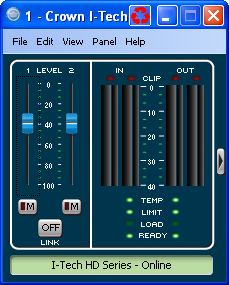
The Basic View Factory Panel will provide you with a reduced level of detail for the product panel. The purpose of this panel is to allow you to quickly see the status of the amplifier without seeing the signal flow. It contains the following information:
The level controls have a displayed range of -100dB to 0dB. These controls, which are a vertical fader, are connected to the appropriate Channel Output Attenuator Fader. There is an annotated scale for showing the range or control.
The Channel Output Mute control is attached to latching On/Off buttons with a dim or dark red indicator when the channel is unmuted and bright red when it is muted.
The Input Level Meters are attached to the Channel Input Router Level Meter. It is actually composed of two meters which show the Peak and the RMS level for that signal. The two indicators will be green in color, but not the same color. There is an annotated scale for showing the level range, which will run 0 to -40dBFS.
Placed above the Input Meters are Input Clip indicators. These LED indicators turn red while a clip event is taking place.
The Output Level Meters also show both Peak and RMS level for the output. These meters are connected to the Amp Output Voltage level and will be blue, but not the same color. There is an annotated scale for showing the level range, which will run 0 to -40dBFS
Placed above the Output Meters will be Output Clip indicators. These LED indicators will turn red while a clip event is taking place.
There are LED indicators for the amplifier status. The four indicators, from top to bottom, for each channel are:
The indicator will display green if the amount of thermal headroom used is less than or equal to 60%, yellow is between 60% and 80%, and red if greater than or equal to 80%.
The LED indicator turns yellow anytime gain reduction is greater than 0 and less than 20dB throughout the signal path. It will turn red when the gain reduction is greater than 20dB.
The Load Status indicator will display one of three colors. The indicator will display green if the Load Status is within the defined range, yellow if the load is below the lower threshold, and red if the load is higher than the upper threshold.
The LED indicator will illuminate green when the amplifier channel is enabled and ready to pass audio. It does not indicate if the amplifier is muted.
You will see a graphic that indicates the panel can be expanded to the Normal View. Clicking this button will change the panel view to Normal View. This control will not be available on a custom control panel, so it will be excluded from the “Convert to Custom Command”.
There is a link button to link the two Input Faders together; this will not affect the mute states. These two faders will retain their relative offset. There is also an indication on the control as to whether or not the two faders are linked together.
If you are connected to the Internet you can find a video overview of this feature at:
http://www.crownaudio.com/tutorials/