Certain HARMAN devices such as the Soundweb London BLU-805 and BLU-325 are capable of sending and receiving Ethernet AVB audio. AVB, or Audio/Video Bridging, is a common name for a set of IEEE standards that ensure the transmission of high quality streaming audio and video over a standard Ethernet connection.
Note: Soundweb London devices cannot send, receive, or process video data.
As a networked audio transport, AVB is similar to CobraNet in many ways, with a few key differences:
Non-proprietary, based on open standards
Guaranteed delivery of media
No need to specify “multicast” or “unicast” transmissions. Any transmitted AVB stream can have 1 or more receivers. Unlike CobraNet multicast bundles, AVB streams with multiple receivers will only transmit to those receivers, and they will not needlessly broadcast across the entire network
Simplified network switch management due to the above three bullets
Reduced latency
Latency range for CobraNet in Soundweb London: 1.33ms – 5.33ms
Latency range for AVB in Soundweb London: 0.5 - 2.0 ms
Increased audio I/O capability per device
Max CobraNet audio channels in Soundweb London: 32x32 per device
Max AVB audio channels in Soundweb London: 64x64 per device
The AVB standards were created through a consortium of industry experts which was then ratified and accepted by the IEEE industry standards body. This means that AVB is not just another proprietary non-standard protocol that floats on top of the Ethernet layers. AVB is the Ethernet. The big difference between AVB and previous solutions for network streamed media (such as CobraNet) is that the IEEE controls the Ethernet standards, which allowed for the specifications of not just the endpoints, but more importantly the switches. This allows an entire network to be designed to accommodate audio and video, with compatibility between AVB devices that are made by different manufacturers.
The standards specify a means to provide time synchronized low latency audio and video over standard CAT5e cable. The majority of the bandwidth across the network is reserved to carry audio and video, and to guarantee the arrival of a signal
In order to accomplish transporting the large amount of information required by both audio and video across a network, bandwidth is reserved through the entire network path. 75% of network bandwidth is exclusively saved for media, both audio and video, to guarantee precisely synchronized audio/video without interruption from non-time sensitive data and communication, like email.
Every audio/video sample is time-stamped with exactly what time to play, and all AVB devices are synchronized to a common time base in order to synchronize multiple streams of audio and video so that they can be rendered correctly in time with respect to each other.
An AVB network inherently supports multiple simultaneous sample rates and (sample) clock sources which allow video and audio streams to be synchronized even though they travel on different paths with different sample rates.
Details for the seven IEEE audio/video bridging standards are available at ieee.org and avnu.org
Add an AVB compatible device to the venue explorer and open the BLU device panel.
AVB Output/Tx Channel Assignment
AVB Input/Tx Channel Assignment
Transmitters have output Channels and Receivers have input Channels. AVB Signals from Transmitters can be routed to any input Channel on a Receiver. The aggregate of these Signals is called a Stream. Currently, routing is a fixed quantity of one channel per stream.
To utilize AVB, the AVB processing objects must first be added and the channels need to be assigned.
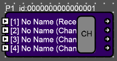
Click the CH button on the AVB Output/Tx object.

This brings up the Define AVB Stream window.
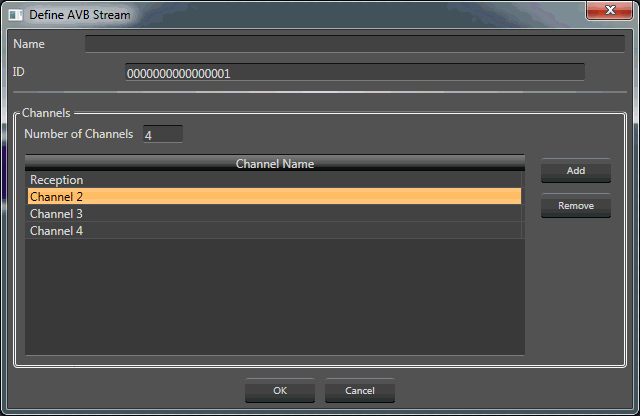
Type in the number of channels required. In this example, four channels have been added.
Name: The name of the AVB data stream
ID: The ID number of the AVB data stream.
This stream ID number will be shown in the AVB Input/Rx window.
Number of Channels: Indicates the number of channels. The channel number may be manually entered here.
Channels are named by double-clicking on the Channel Name and entering in a new name.
Add: Click this button to add channels
Remove: Removes the selected channel.
Double clicking on the object brings up the AVB Output/Tx object window (shown here with four channels):
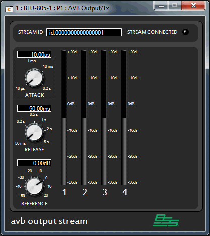
The controls shown (Attack, Release and Reference) are for the meter ballistics. When online and signal is present, the meters will indicate channel levels and the Stream Connected LED will light.
Click the CH button on the AVB Input/Rx object.

This brings up the AVB System Streams window. Here the signals are routed from another AVB device into this device.
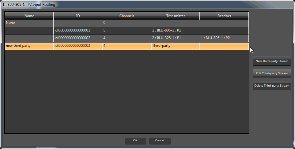
New Third-party Stream: Brings up a window to add and configure a new Third-party stream.
Edit Third-party Stream: Brings up the previously configured Third-party stream window for editing.
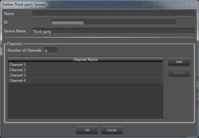
Delete Third-party Stream: Deletes the selected Third-party stream.
AVB Input/Rx Processing Object
Double clicking on the object brings up the AVB Input/Rx object window (shown here with four channels):
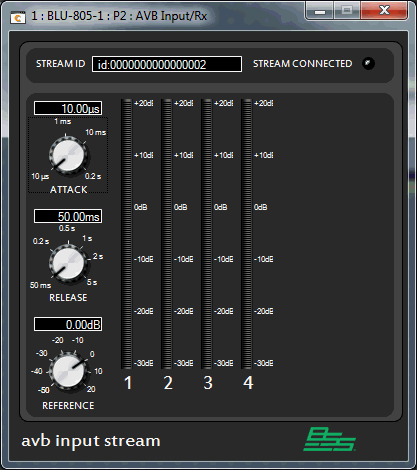
The controls shown (Attack, Release and Reference) are for the meter ballistics. When online and signal is present, the meters will indicate channel levels and the Stream Connected LED will light.