The Contrio Wall Controllers are a range of Ethernet wall mounted controllers with programmable buttons and rotaries. They can be configured using HiQnet Audio Architect to control parameters on any HiQnet device. The controllers connect to a controlled device via Ethernet using Cat 5 cable and support Power over Ethernet (PoE).
Each controller will incorporate one or more of the following depending upon the model.
· Locate Button (all controllers)
· Encoder with Push Button and Light Ring – Dual function encoder providing rotary and push button control. An RGB light ring around the encoder provides metering as well as other user programmable functions.
· Selector Buttons – RGB LED-c buttons.
· LCD display – four sections correspond with the four selector buttons. Can be programmed to display text or graphic icons.
There are currently four Contrio Wall Controllers available:
EC-V
Ethernet controller with a single programmable rotary encoder. Three parameters can be assigned to the encoder, one for the rotary, one for the push button and one for the meter.
EC-4B
Ethernet controller with 4 programmable backlit buttons and LCD display. One 2 state parameter, a preset or a source select can be assigned to each button.
EC-4BV
A combination of the EC-V and EC-4B. Ethernet controller with a programmable rotary encoder and 4 programmable backlit buttons with LCD display. Three parameters can be assigned to the encoder, one for the rotary, one for the push button and one for the meter. One 2 state parameter, a preset or a source select can be assigned to each button. The wall controller can be operated in either ‘Single Zone’, ‘Four Zone’ or ‘Hybrid’ mode.
EC-8BV
A combination of the EC-4B and EC-4BV. Ethernet controller with a programmable rotary encoder and 8 programmable backlit buttons with LCD display. Three parameters can be assigned to the encoder, one for the rotary, one for the push button and one for the meter. One 2 state parameter, a preset or a source select can be assigned to each button. The wall controller can be operated in either ‘Single Zone’, ‘Four Zone’, ‘Eight Zone’, ‘Four by Four’ or ‘Hybrid’ mode.
EC-V EC-4B EC-4BV

EC-8BV
Connecting to a Contrio Wall Controller
When the Contrio Wall Controller is first powered up on a network, it looks for a DHCP server. If a DHCP enabled switch has been implemented on the network the Contrio Controller will be assigned an IP address from the DHCP server. If no DHCP server is present, an Auto IP address will be assigned.
The PC running HiQnet Audio Architect should be on the same network as the controllers. Once the setup is complete the controllers will show up in HiQnet Audio Architect NetSetter View and Discovered Devices View.
Using NetSetter the Wall Controllers can be also configured to use static IP. See the NetSetter Grid section.
Note: After changing the network settings between DHCP, Auto IP and Static IP, the wall controllers need to be restarted to acquire the IP Address.
If it becomes necessary to reset the wall controller to its default network settings (for example, if an incorrect or unknown IP address or subnet mask is configured), see the Factory Reset & Restart section.
The network settings of the Contrio Wall Controllers may be changed in the HiQnet Audio Architect NetSetter.

The operations that can be performed using NetSetter are
Locate the device on the network
Change the device's settings:
o Change the device name
o Change the device HiQnet address
o Configure the device to use AutoIP or DHCP addressing
o Configure the device to use a Static IP address
Wall Controller Configuration
The controls on each of the wall controllers can be configured as follows:
Continuous parameters such as gains and faders can be assigned to the rotary encoder
Binary (2 state) parameters such as mutes can be assigned to the encoder push button
Meters can be assigned to the encoder ring.
2 state parameters such as mutes can be assigned to each button
Presets can be assigned to each button
input number from a source selector to a button
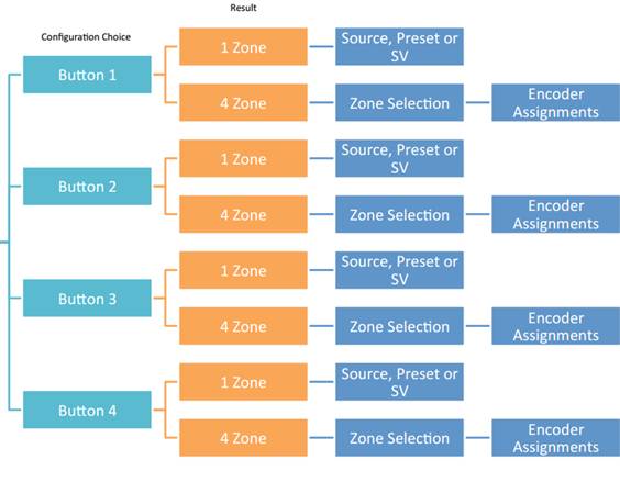
The EC-4B can be configured to operate in one of three modes. These are:
Single zone mode - In single zone mode the controller has 4 assignable buttons and an assignable rotary encoder. This mode is intended for control and monitoring of parameters and recalling presets in a single zone.
o Continuous parameters are assignable to the rotary encoder
o Meters are assignable to the encoder ring
o Binary (2 state) parameters are assignable to the encoder push button
o Binary (2 state) parameters are assignable to each of the 4 buttons
o Presets are assignable to each of the 4 Buttons
o Input number from a source selector to each of the 4 Buttons
Four zone mode - This mode is intended for control and monitoring for up to four zones. Zone selection is made using the four push buttons. In four zone mode the controller has a single encoder for each zone.
o Continuous parameters are assignable to the rotary encoder
o Meters are assignable to encoder ring
o Binary (2 state) parameters are assignable to the encoder push button
Hybrid mode – This mode is a combination of the above and as such allows for more flexibility. In hybrid mode each button can be set to be either Direct Function or Zone Select.
o Direct Function - The button behaves as in Single Zone mode and can have a single parameter assigned to it
o Zone Select – The button behaves as in Four Zone mode. The button selects the zone which has a single encoder
The EC-8BV can be configured to operate in one of five modes. These are:
Single zone mode - In single zone mode the controller has 8 assignable buttons and an assignable rotary encoder. This mode is intended for control and monitoring of parameters and recalling presets in a single zone.
o Continuous parameters are assignable to the rotary encoder
o Meters are assignable to the encoder ring
o Binary (2 state) parameters are assignable to the encoder push button
o Binary (2 state) parameters are assignable to each of the eight buttons
o Presets are assignable to each of the 8 Buttons
o Input number from a source selector to each of the 8 Buttons
· Four zone mode - This mode is intended for control and monitoring for up to four zones. Zone selection is made using the four push buttons on the left panel. Each of the four zones has four programmable button control and single encoder control.
o Continuous parameters are assignable to the rotary encoder
o Meters are assignable to encoder ring
o Binary (2 state) parameters are assignable to the encoder push button
o Binary (2 state) parameters are assignable to each of the four buttons
o Presets are assignable to each of the four Buttons
o Input number from a source selector assignable to each of the 4 Buttons
· Eight zone mode - This mode is intended for control and monitoring for up to eight zones. Zone selection is made using the eight push buttons. In eight zone mode the controller has a single encoder for each zone.
o Continuous parameters are assignable to the rotary encoder
o Meters are assignable to encoder ring
o Binary (2 state) parameters are assignable to the encoder push button
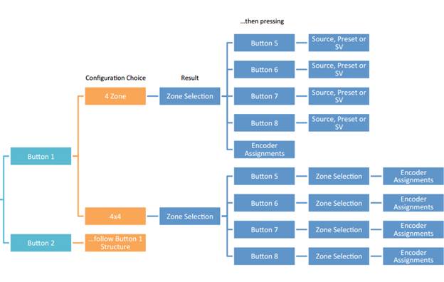
· Four by Four mode - This mode is intended for control and monitoring for up to sixteen zones. There are four main zones with four subzones in each zone. The four main zones selection is made using the push buttons on the left side of the controller. The subzone selection is made using the four push buttons on the right left side of the controller. Each of the sixteen zones has a single encoder controller.
o Continuous parameters are assignable to the rotary encoder
o Meters are assignable to encoder ring
o Binary (2 state) parameters are assignable to the encoder push button
Hybrid mode – Hybrid mode is a combination of the above and as such allows for more flexibility. In hybrid mode each button on the left side of the controller can be assigned to be either Four Zone or Four by Four.
o Four Zone assignment- when the button is selected the right side of the controller will have four programmable button control and single encoder control.
o Four by Four assignment– when the button is selected the right side of the controller will have four sub zones, selectable by each of the buttons. Each sub zone has a single encoder control.
![]()
The Contrio Wall Controller control panel can be launched by right clicking on its icon in Audio Architect and selecting ‘Show Default Control Panel’.
The image above shows the EC-4BV control panel.
The EC-V panel does not have the ‘Label Max Brightness’ or the ‘Encoder Max Brightness’ controls.
The EC-4B does not have the ‘Encoder Max Brightness’ control.
Operations that can be performed:
Configure the Sleep settings for the device:
Enable Sleep (On / Off)
Sleep Delay in seconds
Enable Lockout of Wall Controller unit on sleep.
Lockout Active
Lock or Unlock the wall controller
Configure the maximum brightness settings
1 (dim) to 4 (bright)
Sleep Enable
When enabled, the Sleep function allows the Contrio controller's LEDs and display to 'sleep' (turn off) after a specified period of operator inactivity, which can be entered in the 'Sleep Delay' field. Any button press or rotary movement by the operator will 'wake up' the controller and restore the display and LEDs to show current system status. Note that there is a 2 second delay after 'wake up' before the controls will again become active.
Sleep Delay Time
This is only valid when Sleep is enabled. This field allows you to enter the amount of time it will take, after no operator activity, before the controller will go to 'sleep' by extinguishing its LEDs.
Lockout on Sleep
If 'Lockout On Sleep' is enabled, then, when the controller 'wakes up', it will automatically enter its 'locked' state. Button and rotary actions on the unit will have no effect until the required security PIN number is entered. See Lockout Active for further information.
Lockout Active (Excludes EC-V/EC-V-EU Models)
The 'Lockout Active' button on the Contrio Default Control Panel provides a mechanism to disable thecontroller until a security PIN is entered. This might be appropriate when the controller is located in a public area and restricted access to the controller functions is required. When the unit is 'locked', any button press or rotary movement will be ignored.
Setting the Contrio Wall Controller Lockout PIN
The 4-digit security PIN for a Contrio controller is configured from the controller's 'Properties' section from within Audio Architect. Click on the controller in the venue view to see its configuration properties. A combination of digits 1, 2, 3, and 4 can be used to set the Lockout PIN. This security PIN only becomes active on the controller only when the Lockout Active button is enabled and after going online and loading the design file to the controller.
To unlock a locked controller:
While the controller is in the 'locked' state, either press any button or turn the rotary encoder. All LEDs on the controller will flash RED, indicating it is locked and the message 'Controller Locked – Push and hold any button to enter PIN' will be displayed.
The numbers 1, 2, 3, and 4 will be displayed next to the buttons. Simply press the corresponding buttons to enter the PIN sequence.
When a correct PIN sequence is entered, all LEDs on the controller will flash GREEN twice, confirming the unit is now 'unlocked' and normal operation of the buttons and rotary control will be possible until the unit goes back to 'sleep' after the specified sleep time.
Note: If the PIN sequence entered is incorrect, the controller will flash RED twice, indicating it is still in the 'locked' state and the above procedure must be performed again.
To unlock a Locked Contrio Wall Controller via Audio Architect
You can use Audio Architect to unlock a currently locked Wall Controller (e.g. If you have forgotten the Lockout PIN).
Load the Audio Architect (AA) design file which matches the controller.
From the main AA view, left-click on the corresponding controller.
In the 'Properties' window select the Configuration Tab then delete all characters from the 'Lockout PIN' field.
In the main view, right-click on the controller and select the 'Show Default Control Panel' option.
Disable both the 'Lockout on Sleep' and 'Lockout Active' buttons.
Go online and load the design to the Contrio controller.
The controller will now be unlocked.
LED Maximum Brightness
There are 4 selectable brightness levels for a Contrio controller, they are: LED Maximum Brightness 1 (dim) to 4 (bright). These values can be changed in the controller's Default Control Panel, which is accessed by right-clicking on the controller from the main view in Audio Architect and selecting the 'Default Control Panel' option. Here are a few things to note about LED functionality and the Maximum Brightness parameter:
Disabled controls, such as unavailable channels on a source selector, will be unlit.
Inactive but selectable controls will be unlit (e.g., where a controlled parameter has gone offline).
Active or selected controls will be shown using the currently selected 'LED Maximum Brightness' setting.
In most cases, it is recommended that a high Maximum Brightness setting be used (e.g., 4), as this will allow a higher contrast between active and inactive LED states.
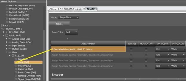
The mapping of wall controller hardware controls onto control parameters and presets is performed by a 'drag and drop' method from a control parameter in Audio Architect to the Contrio Wall Controller configuration page. Double click on the controller on the Venue View to access this page. Parameters to be mapped can be dragged from the Venue Explorer view and dropped onto the control to be assigned.
OR
Controls can be dragged directly from the control panel of a processing object with the desired control to be mapped by holding down CTRL whilst dragging the control. It can then be dropped onto the control to be assigned.
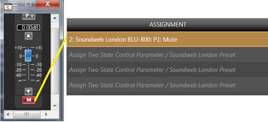
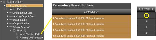
Any input from a source selector can be assigned by dragging the source select input number from the venue explorer in Audio Architect and dropping onto a button. The input source to be selected should be entered in the ‘Input Value’ field.
Configuring the Contrio Wall Controller Control
The configuration page can be accessed by double clicking on the Wall Controller in the Venue View from within Audio Architect.
The Wall Controller configuration settings can be categorized into three sections
· Zone
· Encoder
· Buttons

Zone
· Renaming Zone - To rename a Zone tab, double click on the tab to highlight it, enter the zone name.

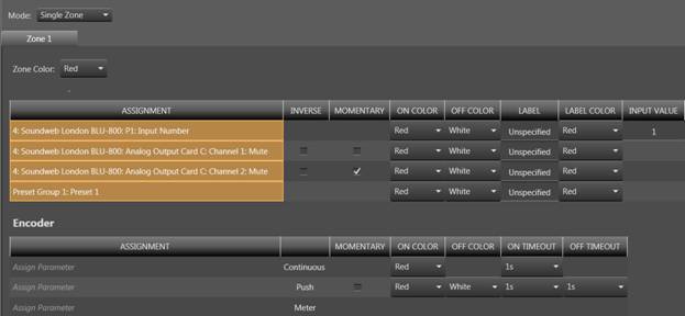
· Mode – this is only available for the EC-4BV. Choose between Single Zone and Four Zone. See EC-4BV section.
· Zone Color – Any one of 8 colors can be selected which will be applied to all LEDs for the zone. This is the default color for all controls but can be over-ridden for each individual control. A different color can be chosen for each zone when in four zone mode.
Available colors are red, yellow, green, cyan, blue, magenta, white or amber.
Encoder
· Momentary (applies to the push button only) – check this box to set the behavior of the encoder push button as momentary. When unchecked the control is latching i.e. remains in the ON or OFF state until the push button is pressed again.
· On Color – This sets the color that the encoder ring will display depending on the state of the assigned parameter. Each control – rotary, push button or meter – can have its ‘On’ color individually set. The actions are as follows:
o Rotary – the encoder ring will display the ‘On Color’ selected for the continuous control while the parameter is being changed. The color will then persist for the duration of ‘Timeout’ and will then revert to the meter color.
o Push Button – the encoder ring will display the ‘On Color’ selected for the push button when the parameter is set to ‘On’. For a latching push button the ‘On Color’ will persist for the duration of ‘Timeout’. For a momentary button the color will persist as long as the button is pressed down.
o Meter – the encoder ring will default to the ‘On color’ set for the meter.
· Off Color (applies to push button only) – This sets the color that the encoder ring will display when the push button goes into its ‘Off’ state. For a latching push button the encoder ring will display the ‘Off Color’ for the duration of its ‘Timeout’. For a momentary button the encoder ring will display the ‘Off Color’ for the period of its ‘Timeout’ after the button has been released.
· Timeout – Five discrete timeouts can be selected. This determines how long the encoder ring will display the selected ‘On’ and ‘Off’ color during or after a change to the rotary or push button. The encoder ring will then revert back to the meter color.
Parameter Preset / Buttons
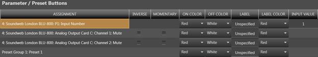
· Inverse - Any 2 state parameter assigned to a button can be programmed with Inverse or Normal Behavior. When the checkbox is enabled the button is assigned for Inverse behavior and when unchecked for Normal behavior.
· Momentary - Any 2 state parameter assigned to a button can be programmed with Momentary or Latching behavior. When the checkbox is enabled the button is assigned for Momentary behavior and when unchecked for Latching behavior.
· On Color and Off Color – ‘On’ color defaults to the zone color and ‘Off’ defaults to white unless another selection has been made. There are eight selectable color options, red, yellow, green, cyan, blue, magenta, white and orange as well as ‘Off’ or no color’. These colors are reflected on the buttons to represent the state of the parameters or presets.
· Label – Each button can be labelled. When the configuration is loaded onto the controller the labels are displayed beside each button. Up to 16 characters can be displayed over two lines for each button.
· Label Color – The color of the label as displayed on the controller can be selected or alternatively ‘Off’ can be selected for no color. Otherwise the label color will default to the zone color.
· Input Value – This is only valid where a source selector has been assigned to one of the buttons. The Input Value selects which source is to be recalled when the button is pressed. Only valid values for the source select inputs are allowed.
If the firmware version is greater than that currently on the Contrio Wall Controller, Audio Architect will automatically detect this when going online and will prompt to go through the firmware upgrade process. Alternatively, the firmware upgrade process can be manually initiated by clicking on the Firmware update button in the Tools section of the Offline Design ribbon in Audio Architect.
The Contrio Wall controller has a pinhole locate push button on the faceplate that will trigger the locate function. Pressing the locate button using a small, long object, such as paperclip, will cause a controller front panel LED’s to flash. If the controller is programmed and online with Audio Architect, the corresponding controller icon will also flash in audio architect design file to identify it.
Wall Controllers can also be located using the locate option in NetSetter with Audio Architect. When the locate function is activated in Audio Architect the controller’s LEDs will flash to indicate that the wall controller is being located from the software.
On controllers with a display, controller information such as IP address and subnet mask can be displayed by entering Boot Menu Mode. This information can be used for installation and troubleshooting purposes and, once installation is complete, can be locked out from within Audio Architect to keep network address information private.
To access and use the Boot menu:
Power off the Controller.
Apply power to the controller while pressing and holding the Locate button. Keep the Locate button held for about 30 seconds.
Press the corresponding button to select the desired menu option.
NOTE: The Ethernet Contrio controllers (with the exception of the EC-V model) also have available Demo Modes which can be used to simulate each controller's control capability. In the event you find the controller behaving strangely after accidentally entering this mode, simply power cycle the device to exit Demo Mode. This mode is generally reserved for sales associates and serves no practical purpose during installation.
The Factory Reset will revert the controller back to its unconfigured, factory-default state by deleting its configuration and clearing any set IP address information.
To Factory Reset a controller:
Power off the controller.
Apply power to the controller while pressing and holding the Locate button. Keep the Locate button held for about 30 seconds.
If using an EC-V, the controller will now perform the Factory Reset and you don't need to perform any of the following steps. If using the EC-4B,EC-4BV, or EC- 8BV, the Boot Menu options should now be displayed and you can continue to step 4.
Select the 'Factory Reset' option by pressing the corresponding button.
Note that selecting the 'Restart' option will restart the controller without clearing the configuration and IP address.
The Factory Reset will now be performed.
Perform the Restart procedure if an Ethernet Conrtio Wall controller becomes unresponsive. This procedure will restart a controller without having to disconnect power to the device. Configuration and IP address information will not be lost when performing a Restart.
To Restart a controller:
Press and hold any button or encoder for approximately 20 seconds.
The controller will now power cycle and reboot with the current configuration and IP settings.
NOTE: There is no Restart procedure for the EC-V controller. To Restart an EC-V controller, power must be disconnected from the controller then reconnected, or the PoE device supplying power must be power cycled.
Maximum network cable length: 328ft (100m)
Power Consumption: 300mA max at 48Vdc
Recommended Ethernet Cable Wiring: VW-1 Rated, 48Vdc, 13W