OVERVIEW
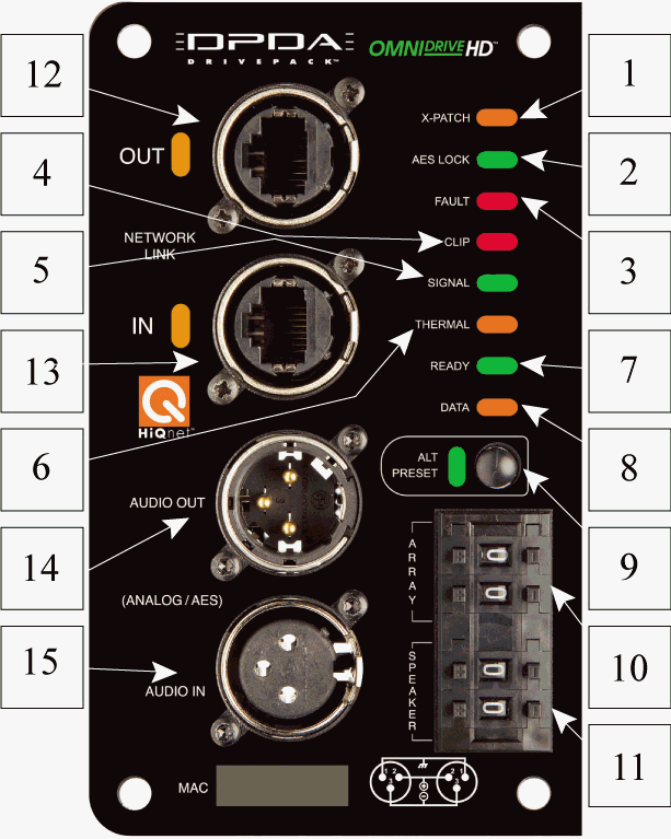
The DPDA Input Module can be used as a retro-fittable sub-assembly with any JBL DrivePack-equipped speaker system. Upgrading to the DPDA module provides powered loudspeaker system users with AES/EBU digital audio capabilities, the sonic benefits of advanced signal processing features, and a variety of input and connectivity options.
Its onboard 100 Mb Ethernet networking switch with daisy-chain capability allows for Remote Control and Monitoring via HiQnet System Architect™ software. Additionally, a rotary mechanical encoder switch allows for array identification and box positioning, up to 99 different speaker positions within each of 99 different speaker arrays or groups.
Twenty, type-selectable input filters (10 System and 10 Guest filters) are available for system equalization along with user-adjustable input delay of up to 2 seconds and sub filter access (user-adjustable low pass filter for subwoofer systems; high pass filter for full-range systems). Signal generator functions (sine wave, swept tone, pink or white noise) are available to facilitate system testing and up to fifty presets can be stored internally.
In addition, Master Control Panels and Master Monitor Panels within System Architect software allow for convenient grouping of control and monitoring functions for multiple JBL DrivePack enclosures with DPDA input modules. This functionality provides a powerful remote control/monitoring interface that is especially useful when working with larger multi-box line array or subwoofer systems.
The HiQnet System Architect™ software user interface provides remote access to the controls, displays and digital speaker preset files available in the JBL DrivePack® Software Control Panel
FEATURES
- HiQnet system compatibility for use in conjunction with other Harman Professional audio products
- AES/EBU digital audio, 96kHz sampling rate
- BSS Omnidrive HD signal processing with F.I.R./I.I.R. filters and LevelMax multi-stage limiting circuitry
- Twenty type-selectable input filters for system equalization; adjustable input signal delay
- 100 Mb native Ethernet switch with daisy-chain capability enables remote control and monitoring
- Fitted with both Ethercon connectors and XLR connectors; multiple signal path and connectivity options
- Mechanical encoder for pre-setting array identification and box positioning when PC or electricity are not available
- Speaker-specific device control interface panels for use within Harman’s
- HiQnet System Architect™ software
INDICATORS
If active, AES audio and HiQnet/network is daisy-chained via Ethercon/RJ45 out connector.
If active, indicates AES sync has been detected and input card has locked to it.
CONTROLS
a) Press and hold for 3 seconds.
b) When LED is active, the alternate preset with 80Hz high pass has been recalled or loaded. On subwoofers, the preset with 80Hz low pass is recalled.
b) User can manually set all speakers to be in the same array or cluster via the rotary dial.
(speakers must be daisy-chained for software to determine their location).
b) User can manually determine the position of the speakers within the array via the rotary dial.
Example B: "01 01" would be Array ID #1, speaker on position #1 (top) etc.
Click here for more information on Array ID/Loudspeaker ID Settings
CONNECTORS
a) Analog mode: passive pass through
b) AES mode: 110 ohms, buffered
a) Analog mode: Balanced , 20Kohms input impedance
b) AES mode: Differentially balanced, 110 ohms input impedance
