The LevelMAX™ limiters were developed in conjunction with JBL Professional to provide maximum transducer performance with full protection. Unlike previous protection schemes, all of the processing items are aware and interact with one another to provide maximum protection.
When using LevelMAX in the CTs 2 Channel Amplifiers with a PIP USP4 Module it is necessary to place the amplifier in fixed 26dB gain mode.
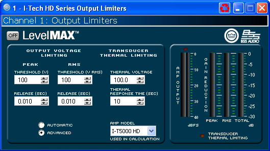
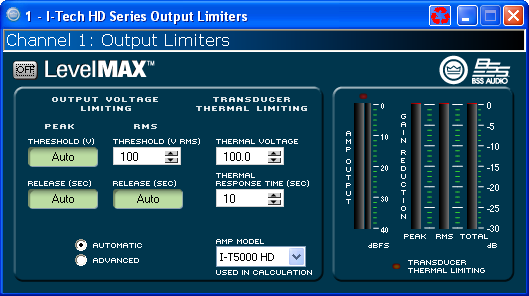
One can select between a fully automatic mode or an advanced mode of operation. In the Automatic mode the variables that are required to be entered are RMS Voltage Threshold, Thermal Threshold, and Thermal Response Time values. In Advanced mode in addition to these parameters, one must set the Peak Voltage Threshold, and both release times. Within the firmware the remaining values are calculated. The controls available are:
If you need to calculate voltage values from wattage ratings it can be done using this formula:
![]()
When working in an offline mode there is also a drop down box for the amplifier model. This information is needed to allow for the software to properly calculate the values of the LevelMAX suite. When working online, connected to a system, this information is gathered by querying the amplifier for the model information directly.
The Peak Voltage value is the maximum Voltage that the amplifier will provide at the output. This value should be set based on the recommendations of the speaker manufacturer. The parameters are:
This is the value based on the output of the amplifier. If one has more than one driver in parallel the value still remains the same at the maximum value from the manufacturer.
This value is calculated within the processing automatically.
In Automatic mode this value is calculated within the amplifier based on the band pass and threshold. In Advanced mode one can change how long the limiting will be engaged after a peak has passed.
The RMS Voltage Limiter block provides controls allowing you to base limiting on the RMS (Root Mean Square) power of the output signal through the amplifier. This value is often referred to as the "program" level of the driver.
This is the value based on the output of the amplifier. If one has more than one driver in parallel the value still remains the same at the maximum value from the manufacturer.
This value is calculated within the processing automatically.
In Automatic mode this value is calculated within the processing automatically. In Advanced mode one can change how long the limiting will be engaged after a high energy passage has passed.
These controls allow one to compensate for how a driver will react as it heats up.
This meter shows the output level of the amplifier for reference purposes.
There are three meters that show the gain reduction that is currently taking place. The three meters allow one to look at the reduction as either the amount of Peak reduction, RMS reduction, or the calculated value of the two working together.
This LED will turn green when the amplifier has calculated changes to the limiting based on the driver heating up.
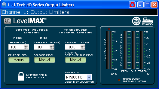
If custom tunings have been created for the amplifier, typically a tuning file, it is possible that the limiter settings will be placed into a locked mode indicated by the Lock icon on the form. In this mode only the unlocked values may be changed.
If you are connected to the Internet you can find a video overview of this feature at:
http://www.crownaudio.com/tutorials/