Master Speaker Panel
JBL DrivePack®
For help on creating master control panels see Create Master Control Panels.
Overview:
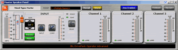
The JBL Master Speaker Panel hosts controls that are generic among all JBL DrivePack enabled speakers.
JBL Master Control Panels provide a quick and effective way to control and monitor your entire HiQnet system in groups and sub-groups of the JBL devices available on the network. Functionality of JBL Master panels is the same as individual product panels, however there are some differences and limitations.
JBL Master Speaker Panels allow for the control of multiple like and non-like JBL devices. It is possible to combine for example multiple VT4888DP-AN and VT4887ADP-AN devices into one panel. The limitation here is that the number of controls available in the master control panel is reduced as non-identical JBL devices are combined into a single master control surface.
Processing panels such as Compression and Delay indicate the settings for the first device added to the Master Panel. Typically these will be the same values for all devices and if the values are different in any device (for any parameter) an alert symbol will appear in the parameter that is not the same across all devices in the group.
The individual processing panels will indicate the settings for the first device added to the Master Panel, typically these will all be the same values, if the values are different an alert symbol will appear in the parameter that is not the same across all devices in the group.
In general, gain or level-type master controls are soft linked and will track offsets in individual devices. Other parameters are hard linked and making a change in a master control panel or master sub-control panel will force that specific parameter value to all devices in the group.
Master Soft-Linked Controls
Changes made in Master Gain Fader or Spinner Box are the same. In the case of gains, each device can be controlled individually by clicking the rectangular area of the slider to open a pop-up that shows individual sliders for each attached device. The sliders and spinners will then maintain the relative offset between devices.
- Input Gain - Functionally the same as Input Gain on individual devices.
- Input Routing Gain - Functionally the same as Input Routing Control on individual devices.
- Compression Threshold - Functionally the same as Compression Threshold on individual devices
- Signal Generator Level Control - Functionally the same as the Signal Generator Control on individual devices
Master Hard Linked Controls:
- CobraNet Input and Source Select - Where applicable
- EQ - EQ filters typically fall into the Hard Link category. Changes made to EQ filters in the master control panel force the value set in the master control to the associated EQ's of all the individual devices in the group. However an exception can be created where an EQ filter can appear to be soft linked. If a filter is enabled in an individual device that is not active in a master control panel, the filter in the individual device will remain offset from the master controller. However, enabling a master EQ with the same filter number and bank as the offset filter in the individual device will force the master value to the individual device.
- Compression - Forces the same compression parameters to all devices in the group. Threshold is excepted and can be soft linked within individual devices.
- Delay - Forces the same delay settings to all devices in the group.
- Foldback (CobraNet only) - Where applicable
- Polarity - Forces the same polarity state to all devices in the group.
- Mute - Forces the same mute state to all devices in the group.
Presets
The functionality of Master Preset control is the same as found in individual devices. However Master Presets offer the additional feature of storing changes made in the master panel either locally or globally in all devices in the master group. Go to help on Master Presets for additional information.
Master Metering
JBL Master Panel meters indicate average levels in the meter bar and also indicate min/max level tick marks within the meter.
Load Status
Load status indicators will display one of three colors and reflects worst case condition of any device in the group.
-
- Green - Indicates that driver load impedance on all devices are within the defined normal operating range.
- Yellow - Indicates that driver load impedance on one or more devices is above the defined normal operating range, i.e. open circuit.
- Red - Indicates that driver load impedance on one or more devices is below the defined normal operating range, i.e. short circuit.
Clip Indicators
The Clip indicator will turn Red when the signal waveform on the corresponding channel of any device in the group is clipping.
Input /Output Meters -
Displays Average, Minimum and Maximum values for all devices in the group.
Gain Reduction Meters -
The protection limiters are engaged when the input or output signal of any device exceeds the defined normal range.