This sub-panel is used to configure the input section of the amplifier. The functionality of basic controls and metering found in the input control block are identical to similar controls and meters found in the Output Control block.
This sub-panel is used to configure the input section of the amplifier. The functionality of basic controls and metering found in the input control block are identical to similar controls and meters found in the Output Control block.
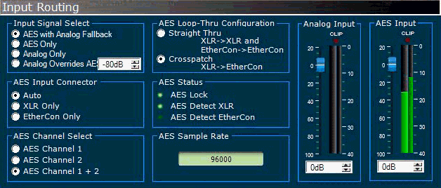
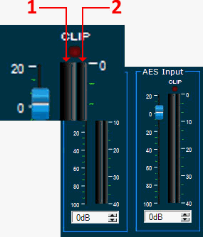
The clip indicator (above the Input Meter) indicates when either the analog or digital signal input level is exceeding limits.
Analog Input – Clip occurs above +26dBu
Digital Input – Clip occurs above 0 dBFS, 7V pk-pk (peak to peak)
 - Detects the input signal of the device is below clipping.
 - Clip detection monitors input and DSP. The indicator color changes to Red when clipping is detected.
This control allows the user to switch between AES with Analog Fallback, AES Only, Analog Only and Analog Overrides AES modes.
AES with Analog Fallback – switches to Analog if AES is not detected.
AES Only – AES is the only expected input
Analog Only – Analog is the only expected input
Analog Overrides AES – AES is primary mode, analog overrides when AES drops below the user defined threshold
AES Input Connector
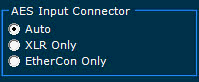
Auto: input card automatically detects the digital audio signal connection.
XLR only: User sets the input card to receive digital audio via the XLR connector.
Ethercon only: User sets the input card to receive digital audio via the Ethercon/RJ45 connector.
AES Channel Select
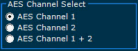
AES digital audio format carries two separate audio channels on the same stream/connector.
CH1: Input card will only process digital audio on CH 1 or Left
CH2: Input card will only process digital audio on CH 2 or Right
CH1+CH2: Input card will sum signal on CH1 with signal on CH 2, or Left + Right
AES Loop-Thru Configuration
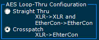
Straight Thru
Crosspatch
(AES audio travels on available CAT-5/6 conductors)
AES Status

AES Lock: LED indicates AES sync has been detected and input card has locked to it.
AES Detect XLR: LED indicates input card has detected AES audio on the XLR input connector
AES Detect Ethercon: LED indicates input card has detected AES audio on the Ethercon input connector
AES Sample Rate
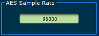
Displays the sampling rate frequency of the AES input signal the input card has locked to. (Typical between 32000 & 96000)

The AES and Analog Faders on the Input Control Panel can be controlled independently, whereas the Normal Panel Input Fader will affect both AES and Analog simultaneously. The user can use these faders in conjunction for better results.
Indicates the pre-input control fader signal level into the analog or digital inputs of the input module in dBFS from –40 dBFS to 0 dBFS. The Input Gain Fader does not affect the level displayed on the Input Meter.
This control allows the user to adjust the active signal level into the amplifier module. The user can use the mouse to increase and decrease the gain by moving the gain slider control up or down or clicking on the up and down arrows of the gain control until the desired gain is attained. The user can also edit this parameter directly by clicking on the gain parameter and modifying the number with the keyboard then pressing "Enter" to activate the change. Adjustment range is –100 dB to 20 dB.
The user can double-click on the COMP button control to configure input compression for the device. When the COMP button control is double-clicked the user is presented with the DrivePack Input Compression control panel.
The user can double-click on the DELAY button control to configure input delay. When the DELAY button control is double-clicked the user is presented with the Input Delay control panel.
The user can double-click on the DELAY button control to configure input delay. When the DELAY button control is double-clicked the user is presented with the Input Delay control panel.

The Input Gain Spinner control allows precision incremental control in 0.5dB steps by clicking on the UP or Down tabs. The spinner control also allows a numerical gain value to be input directly into the text field.
The Ready Indicator indicates that the input module is ready to process input signals.
 - Indicates the self test has completed successfully and that the input module is ready for processing input signals.
 - Indicates the self test is in progress and that the input module is not ready for processing input signals.
 - Device is working within the proper operating temperature.
 -Device is not working within the proper operating temperature.
 - Master Input signal not muted.
 - Input signal muted.
 - Input signal polarity is normal
 - Input signal polarity is reversed