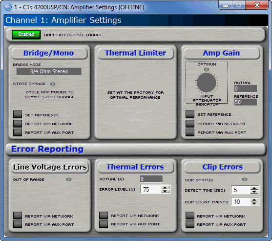
The exact look of the panel will vary if the device is being individually controlled or in a Master Panel. This variance also includes the controls that are included on the Master Panel. Open the Amplifier Settings by double clicking on the AMP button on the main panel.

The amplifier settings page contains seven items pertaining to the actual amplifier, not the processing.
Use this button to turn the high voltage supply for each channel on and off. If the Amplifier Enable is turned off, the front panel ready indicators will turn off and the amplifier channel will not produce any audio
The Bridge Mono panel will show the location of the output mode switch for that channel of the amplifier. The State Change LED will indicate if the switch has been moved without a power cycle of the amplifier.
This displays the location of the input attenuator for that channel on the amplifier. The Optimum LED indicates where the output of the DSP processor and the input of the amplifier are matched to provide optimum signal to noise ratio.
The Thermal Limiter has already been set at the factory for the most effective thermal protection of the amplifier. This setting can not be changed.
The Line Voltage section allows you to monitor the line voltage in real time. The amplifier indicates when the input Line Voltage is outside of acceptable levels. This out-of-range indication can be communicated via the System Architect Event Log or through the Aux port.
Click the "Report Via Network" button in this area so that it is on if you want to have any voltage out-of-range events reported to you via the System Architect Event Log . Click the "Report Via Aux Port"button so that it is on if you want to have any voltage out-of-range events reported through the Aux port of the selected module. Note that for this option to be active you must also set the Aux Output Mode to "Report Errors."
You can choose to be informed through error reporting when a Thermal Error occurs. To enable the reporting, select one of the options for the report. This selection is done by turning on by clicking the button where you would like an error reported. Report Via Network will send a message to the System Architect Event Log indicating that there is a problem. Report Via Aux will cause the state of the Aux port to change. Note that for this option to be active you must also set the Aux Output Mode to "Report Errors."
This control lets you set an acceptable thermal level between 1% and 100%. If the actual thermal level exceeds this setting, an error message will be generated as selected.
This control displays the current thermal level of the channel.
You can choose to be informed through error reporting when an excessive number of IOC or Clip events occur over a unit of time in an amplifier. To enable the reporting, select one of the options for the report. This selection is done by turning on by clicking the button where you would like an error reported. Report Via Network will send a message to the System Architect Event Log indicating that there is a problem. Report Via Aux will cause the state of the Aux port to change. Note that for this option to be active you must also set the Aux Output Mode to "Report Errors."
The Count slider lets you set number of IOC events per unit of time allowed before an error is generated between one and one hundred.
With the time control. you set the number of seconds (1 to 10) during which the number of Clip error events are counted for possible error reporting.