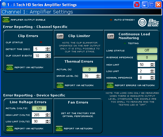
The amplifier settings page contains five items pertaining to the actual amplifier.
The Amplifier Output Enable will turn the high voltage rails of the amplifier on or off. When it is enabled, the rails are energized and the amplifier can produce signal. If this is disabled, the amplifier will not produce audio. This selection is on a channel by channel selection.
The USP4 module has a auto-standby feature that will turn off the high voltage rails of the amplifier
This control allows you to activate or deactivate the Auto-Standby function for a selected amplifier channel.
The threshold control allows you to set an input level threshold between -40 dB to +16 dB. If the input level fails to exceed this threshold for a period of time set by the Turn-off Delay, this amplifier channel will be put into standby.
The Turn-off Delay control lets you set the amount of time for which the input level must remain below the Input Gate Level before the amplifier channel is put into standby. The range of control is 1 minute to 255 minutes.
With the time control, one sets the number of seconds (1 to 10) during which the number of IOC or Clip error events are counted for possible error reporting.
The Count spinner box lets you set number of Clip events within the defined time allowed before an error is generated between one and one hundred.
You can choose to be informed through error reporting when an excessive number of Clip events occur over a unit of time in an amplifier. Report Via Network will send a message to the Event Log indicating that there is a problem.
The Clip Limiter block provides controls allowing you to eliminate clipping through the amplifier. When the amplifier outputs a clipped wave form then output level of the PIP module is reduced to keep the amplifier from clipping.
Click on the enable button to turn the Clip Limiter on and off.This control displays the current thermal level of the channel.
This control lets you set an acceptable thermal level between 1% and 100%. If the actual thermal level exceeds this setting, an error message will be generated if selected.
You can choose to be informed through error reporting when a Thermal Error occurs. Report Via Network will send a message to the System Architect Event Log indicating that there is a problem.
Continuous Load Monitoring allows you to monitor the average impedance of your load and alerts you if impedance falls outside of limits that you have set.
Conditions are not always adequate for load testing. The component reports this through a pair of "Testing" LEDs. These LEDs may be found both on the Load Monitoring Page and on the Basic View of the Control Panel. If conditions are adequate for load testing, these LEDs will be illuminated.
This button activates or deactivates Load Monitoring for the selected channel.
When Load Monitoring is turned on and conditions are sufficient for testing to be taking place, then the Status, shown both on this page and in the Basic View of the Control Panel displays:
Low - displayed if the detected average impedance falls below the prescribed low limit.
Normal -displayed if the detected average impedance falls in the range between the prescribed low and high limits.
High - displayed if the detected average impedance rises above the prescribed high limit.
The average impedance is displayed.
One can define both the high and low impedance limits. If the average impedance goes outside of these bounds while Load Monitoring is enabled, then the High or Low Status message will be shown.
Input a nominal load impedance in ohms. Setting this value determines the resolution of the testing.
This button allows you to direct Load Monitoring status high or low messages to be reported through the System Architect Event Log.
The Line Voltage section allows you to monitor the line voltage in real time. You may also set a high and low limit. You may select to have voltage levels outside of these bounds reported to you via error reporting
Actual Line Voltage is displayed in the Monitor area.
You can set the line voltage limits by using the numeric spin boxes. You select a voltage percentage as maximum voltage and minimum voltage. This protection is in addition to the protection built into the amplifier.
Click the "Report Via Network" button in this area so that it is on if you want to have any voltage out-of-range events reported to you through the System Architect Event Log.
You can choose to be informed through error reporting when there is a fan error. Report Via Network will send a message to the System Architect Event Log indicating that there is a problem.
If you are connected to the Internet you can find a video overview of
this feature at:
http://www.crownaudio.com/tutorials/