The exact look of the panel will vary if the device is being individually controlled or in a Master Panel. This variance also includes the controls that are included on the Master Panel.
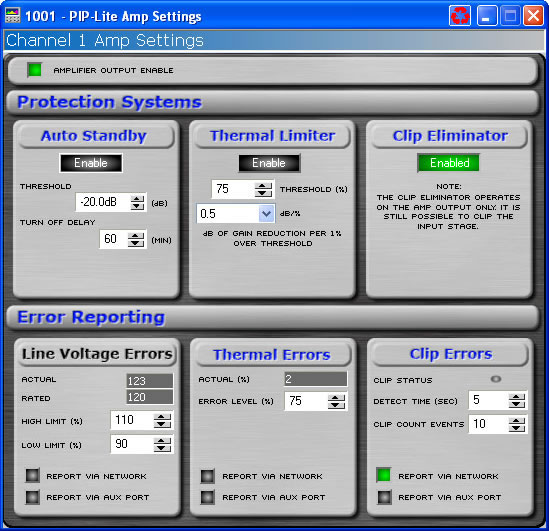
The amplifier settings page contains six items pertaining to the actual amplifier. The controls available in the I Tech Amplifier are different from the controls available in the PIP-Lite, PIP-USP3, and PIP-USP3/CN.
Use this button to turn the high voltage supply for each channel on and off. If the Amplifier Enable is turned off, the front panel ready indicators will turn off and the amplifier channel will not produce any audio
This control allows you to activate or deactivate the Auto-Standby function for a selected amplifier channel.
The threshold control allows you to set an input level threshold between -40 dB to +16 dB. If the input level fails to exceed this threshold for a period of time set by the Turn-off Delay, this amplifier channel will be put into standby.
The Turn-off Delay control lets you set the amount of time for which the input level must remain below the Input Gate Level before the amplifier channel is put into standby. The range of control is 1 minute to 255 minutes.
The Thermal Limiter block provides controls allowing you to base limiting on the thermal energy detected in the amplifier. Thermal limiting is configurable for each channel, independently. Each Thermal Limiter section lets you adjust three parameters:
This control allows you to engage or disengage this feature for the selected channel.
The amount of thermal energy available is 100%. The amount of thermal energy currently being expended will always range between 0 to 100%. You may set an amount, a Threshold, above which limiting occurs. The default level is 75%.
This control lets you set the amount that the input level is attenuated for each percentage point that the thermal energy exceeds the threshold.
The Clip Eliminator block provides controls allowing you to eliminate clipping through the amplifier. When the amplifier outputs a clipped wave form then output level of the PIP module is reduced to keep the amplifier from clipping.
Click on the enable button to turn the Clip Eliminator on and off.
The Line Voltage section allows you to monitor the line voltage in real time.. You may also set a high and low limit. You may select to have voltage levels outside of these bounds reported to you via standard error reporting or through the Aux port of a PIP.
The nominal line voltage of your amplifier is reported to the PIP and is displayed in this section.
Actual Line Voltage is displayed in the Monitor area.
You can set the line voltage limits by using the numeric spin boxes. You select a voltage limit as a percentage of the nominal line voltage.
Click the "Report Via Network" button in this area so that it is on if you want to have any voltage out-of-range events reported to you through the System Architect Event Log. Click the "Report Via Aux Port"button so that it is on if you want to have any voltage out-of-range events reported through the Aux port of the selected module. Note that for this option to be active you must also set the Aux Output Mode to "Report Errors."
You can choose to be informed through error reporting when a Thermal Error occurs. To enable the reporting, select one of the options for the report. This selection is done by turning on by clicking the button where you would like an error reported. Report Via Network will send a message to the System Architect Event Log indicating that there is a problem. Report Via Aux will cause the state of the Aux port to change. Note that for this option to be active you must also set the Aux Output Mode to "Report Errors."
This control lets you set an acceptable thermal level between 1% and 100%. If the actual thermal level exceeds this setting, an error message will be generated as selected.
This control displays the current thermal level of the channel.
You can choose to be informed through error reporting when an excessive number of IOC or Clip events occur over a unit of time in an amplifier. To enable the reporting, select one of the options for the report. This selection is done by turning on by clicking the button where you would like an error reported. Report Via Network will send a message to the System Architect Event Log indicating that there is a problem. Report Via Aux will cause the state of the Aux port to change. Note that for this option to be active you must also set the Aux Output Mode to "Report Errors."
The Count slider lets you set number of IOC events per unit of time allowed before an error is generated between one and one hundred.
With the time control. you set the number of seconds (1 to 10) during which the number of IOC or Clip error events are counted for possible error reporting.