The exact look of the panel will vary if the device is being individually controlled or in a Master Panel. This variance also includes the controls that are included on the Master Panel.
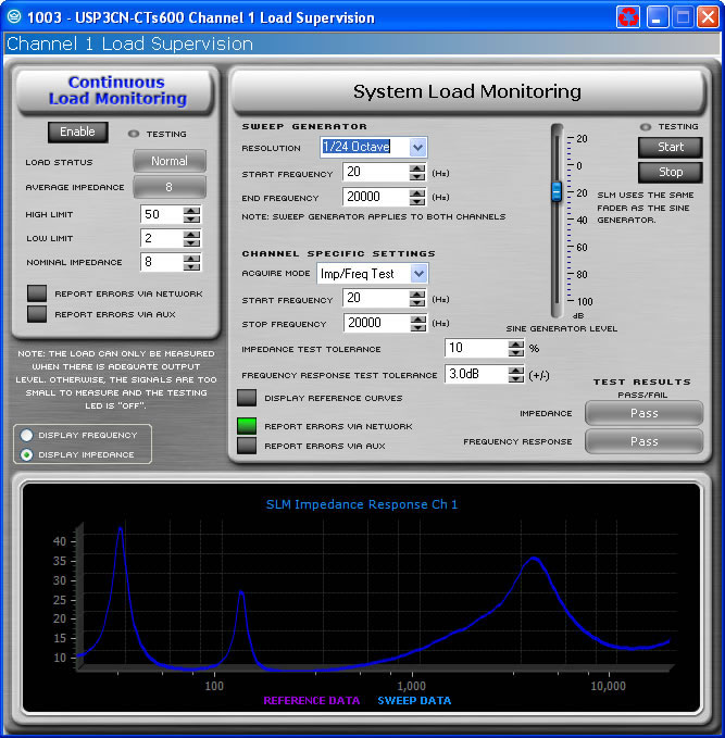
The Load Monitoring Page contains two different types of Load Monitoring controls and test result indicators for each channel of an amplifier. There is the Continuous Load Monitoring and the Sweep Load Monitoring. Continuous Load Monitoring uses the output signal of the amplifier channel to calculate the average impedance of the load attached to it in real time. The Sweep Load Monitoring (SLM) is designed to be a diagnostic tool allowing for the user to test the complete impedance response of the load attached to the amplifier channel;. Using the SLM feature the input signal of the PIP module is muted and the signal is replaced by a swept test tone.
Continuous Load Monitoring allows you to monitor the average impedance of your load and alerts you if impedance falls outside of limits that you have set.
Conditions are not always adequate for load testing. The component reports this through a pair of "Testing" LEDs. These LEDs may be found both on the Load Monitoring Page and on the Basic View of the Control Panel. If conditions are adequate for load testing, these LEDs will be illuminated.
This button activates or deactivates Load Monitoring for the selected channel.
When Load Monitoring is turned on and conditions are sufficient for testing to be taking place, then the Status, shown both on this page and in the Basic View of the Control Panel displays:
Low - displayed if the detected average impedance falls below the prescribed low limit.
Normal -displayed if the detected average impedance falls in the range between the prescribed low and high limits.
High - displayed if the detected average impedance rises above the prescribed high limit.
The average impedance that has resulted in the most recent result is displayed.
The user defines both the high and low impedance limits. If the average impedance goes outside of these bounds while Load Monitoring is enabled, then the High or Low Status message will be shown.
Input a nominal load impedance in ohms. Setting this value determines the resolution of the testing.
This button allows you to direct Load Monitoring status high or low messages to be reported through the System Architect Event Log .
Clicking this button will report Load Monitoring status high or low by causing the Aux port of the PIP to be set high or low depending on the selected Aux Out Polarity.
The SLM feature allows one to measure both the impedance of the load attached to the amplifier channel as well as the frequency response through the internal processing. Sweep Load Monitoring is available for the PIP-USP3 and PIP-USP3/CN only. The USP3 and USP3/CN include a signal generator to provide a swept sine-wave signal for the tests. The controls can be broken down into overall controls and channel specific settings. The overall controls are parameters that effects both channels of the amplifier; the channel specific settings impact only that individual channel.
Once tests are set up, you may initiate a test by clicking on the Start button located at the top of the Control Panel. This will cause a swept sine wave to be generated through each channel at the frequencies and levels defined. In addition this will mute the input signal to the amplifier while the test is being run. While a test is in progress, the text of the Start button will change to "Testing". Once a test is completed, the "Pass/Fail" indicators will be updated accordingly.
Making a change to the overall controls will effect both channels. The overall controls include the following items:
Sweep Generator
Start frequency
Stop frequency
Resolution
Sine Generator Signal Level
Start Button
Stop Button
The sweep generator controls do not define the range of testing, it sets the range for the test tone. The Start and Stop frequency should be set to the widest range for both channels not just for one channel. An example being if Channel 1 is powering the low frequency section of biamplified cabinet and channel 2 is powering the high section, the range should be set for the entire range. The resolution determines how many samples are made across the range for the frequency. The resolution can be set from the drop down list to be between 1/24th of an Octave to a single Octave. In addition to determining how many samples will be made of the system, it also determines how long the sweep will take. The more resolution the longer the sweep will take. These values need to be consistent between tests.
The level of the generator should be set to a reasonable level to provide a good testing signal. The test process requires that enough power is available at the output of the amplifier to provide reliable test data. Also this level needs to be consistent across tests.
The Start and Stop Buttons will initiate or halt a test sweep, it impacts both channels and will mute the input signal for the module to provide a reliable test. Pressing the Start button will result in the process starting and the button text will change to "Testing" while the test is being run. Pressing Stop will halt the test and will result in that test data being discarded.
The channel specific settings include:
This section of the SLM feature allows one to configure the tests. Basically one runs a reference curve on a known good component, then runs tests at a future date. Those test results will be compared to the measured reference values.
The Mode drop-down menu selects the type of test:
Off-Pass means that no testing actually is taking place. The module reports back a "pass" condition so that errors are not triggered.
Off-Report also means that no testing is taking place. The difference is that the result of the last test is what is displayed.
Impedance Test (Imp Test) means that the module measures the impedance of the load currently connected to the amplifier and compares it to the reference curve stored earlier. If it is out of tolerance then the module reports a failure.
Frequency Test (Freq Test) results in the module measures the frequency response of the amplifier and internal processing, and compares it to the reference stored earlier. If it is outside of the tolerance then the module reports an error.
Imp./Freq. Test combines both of the tests above.
Reference measures both the impedance and frequency response of a known good component. All other tests are compared to these results until a new reference is created.
These are the lowest and highest frequencies of the test that is being conducted. It is the range that the load should be expected to reproduce. These need to be set to be within the range of the overall sweep that was set in the Sweep Generatror section.
Use the Impedance Tolerance control to set the percentage of difference by which an impedance test may vary from the reference and still be considered "passing." Tests conducted where the impedance is measured at a percentage outside this tolerance at any point along the frequency range will be considered "failed" for purposes of the impedance test.
Use the Frequency Tolerance control to set the difference in dB by which a frequency test may vary from the reference and still be considered "passing." Tests conducted where the frequency is measured at a dB level outside of this tolerance at any point along the frequency range will be considered "failed" for purposes of the frequency test.
The Display Reference Curves button will determine if the graph at the bottom of the panel will show the reference values or only the results of the most recent test.
If this button is set to the on position, the results of a test are reported in the System Architect Event Log.
If this button is set to the on position, the results of a test are reported via the Aux Out port of the USP3 or USP3/CN. The Aux Out port will be set high if all tests have a Pass result. It will be set low if any of the tests fail.