Display functions directly visible on the JBL Operator Advanced Control Panel include:

The title bar indicates the HiQnet address and speaker type of the device.

Notifies the user of the status of the device. Indicates that the device is connected or disconnected from the network.

Context sensitive tool tips are provided to the user when the user hovers the mouse over a control or status area in the Operator Advanced panel. These tips will help the user determine the proper action to take.

Allows the user to recall or store up to 10 device presets. JBL devices ship from the factory with 2 factory pre-configured presets.
Preset 1 is programmed for the full range response typical for the speaker type and Preset 2 engages an alternate 80Hz Subwoofer filter. The ENABLE ALT PRESET hardware button found on the device input module toggles Preset:1 and Preset:2 directly from the loudspeaker. For more information, see help on Presets.
This control allows the user to put the amplifier in standby mode while the device is still online.
The following processing blocks are accessed by double clicking in the associated button.
Processing sub-panel control buttons include:


Double click on the General button to open the General information sub-panel.
The general settings panel allows the user to set and display information for a particular device. For additional details see Help on the General sub-panel for DPAN devices.

Double click on the General button to open the General information sub-panel.
The general settings panel for DPCN devices provides additional CobraNet information for the device.
The general settings panel for DPCN devices provides the same general information found on DPAN devices and also allows the user to set and display CobraNet information for that device. For additional details see Help on the General sub-panel for DPCN devices.

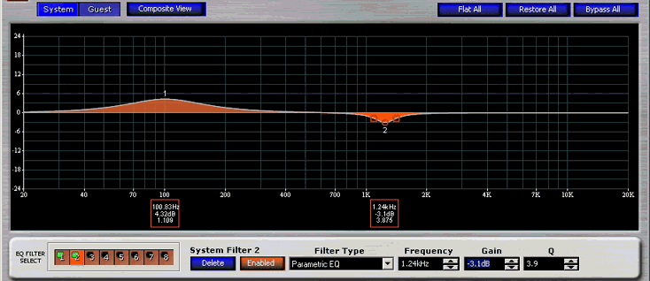
JBL DrivePack® devices all have a total of 16 user accessible EQ filters available for system tuning. The 16 filters are divided into 2 banks of 8 filters each and are assigned to either the System EQ filter bank or the Guest filter bank. The user can modify the EQ filter parameters in an intuitive way by using the EQ Graphical Editor or the direct access text field spinner controls. The user can use the mouse to individually modify both the gain and Q on any of the eight (8) EQ filters in real-time. As the filter is adjusted in the Editor the parameters are modified in the audio DSP to give real-time audio feedback. The frequency scale of the EQ Graphical Editor is logarithmic. The EQ Graphical Editor displays either the System or Guest EQ filters depending on the state of the System/Guest EQ Filter control buttons. All EQ functions and displays for EQ filters are accessed directly from the EQ Graphic Control Panel.
For detailed information on using the device EQ Filters, see help on the EQ Graphic Control Panel.

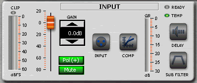
This sub-panel is used to configure the input section of the amplifier. The input control block provides Input Metering, Clip Indicator, Gain Reduction Metering, Ready and Temperature status indicators. Direct access control functions include Input Gain, Input Polarity, and Input Mute. Processing sub-routines include Input Routing, Input Compression, Input Delay and input Sub Filter High-Pass and Low Pass filters. The functionality of the basic controls and metering found in the input control block are identical to similar controls and meters found in the Output Control block.
For detailed information on using the device Input control and monitoring sub-panel, see help for Input Control and Monitor Sub-Panel.

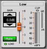
This sub-panel is used to configure and monitor the output section of each discrete amplifier output channel. Each individual JBL DrivePack amplifier channel is optimized for the specific bandpass application to which it is assigned. The associated bandpass is identified by a label located directly above the output control fader. Individual amplifier outputs are not user accessible for crossover design. Specific DSP frequency points and crossover types are applied by JBL Engineering to provide the best possible electro-acoustic response. Controls, meters and indicators are functionally identical to similar functions found on the Input Control and Monitor Sub-Panel.
For detailed information on using the device output control and monitoring sub-panel, see help for Output Control Block Sub-Panel.