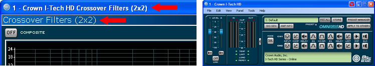
Dual (2 x 2) Mode
The Crossover panel will change depending on what mode the amplifier is in. One changes the mode by using the Amplifier Mode button on the Normal View of the factory provided panel. You can tell what mode the amplifier is in by looking at the top section of the Crossover form. There are four modes the amplifier can be in:
The reason that the mode is important is that there are two FIR processing blocks in the processing engine for the entire amplifier. As one changes the mode of the amplifier, the allocation of the FIR processing blocks to maximize the flexibility and use of these processing blocks. The FIR assignment rules are used for this configurations are:
2 x 2 Mode
There is one FIR processing block assigned per channel.
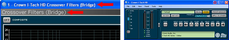
Bridge Mono Mode
Both FIR processing blocks are assigned to the single channel.
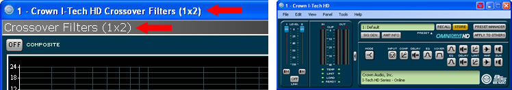
1 x 2 Mode
The FIR processing blocks are assigned differently in unique or duplicate mode. In duplicate mode, both FIR processing blocks are assigned to a single crossover processing block that is then split to both output processing channels. In unique mode there is one FIR processing block per channel, however one can link the High Pass of Channel 1 and the Low Pass of Channel 2 to have the same corner frequency and slopes and only use one FIR processing resource even though it is affecting both channels.
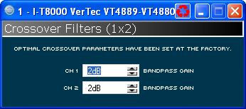
Protected Settings
When using Protected Settings, the person creating the file can lock the Crossover settings. If this has been done, the unprotected Bandpass gain controls are shown on the control panel.
The IIR filters do not have the same restrictions as the FIR filters. All of these rules are verified by the control panel in real time.
There is an additional latency for processing of the FIR filters. This latency is in addition to the other latencies in the amplifier, latency through the DSP section and CobraNet transport latency. One sets the FIR Latency and the corresponding frequency limitations for the FIR filter are displayed on the panel. These limitations do not affect the IIR response filters. This latency affects both channels simultaneously.
|
48kHz Sample Rate
|
|
96kHz Sample Rate | ||
|
Latency
|
Minimum Frequency
|
|
Latency
|
Minimum Frequency
|
|
|
|
|
0.92ms
|
2000Hz
|
|
|
|
|
1.83ms
|
1000Hz
|
|
3.17ms
|
500Hz
|
|
3.67ms
|
500Hz
|
|
6.33ms
|
250Hz
|
|
7.33ms
|
250Hz
|
|
12.67ms
|
125Hz
|
|
14.67ms
|
125Hz
|
|
25.33ms
|
62.5Hz
|
|
29.33ms
|
62.5Hz
|
|
50.67ms
|
31.25Hz
|
|
|
|
There is also a common maximum frequency of 12kHz no matter what the latency is.
There are four quick start buttons down the left side of the control panel that will preload values into the filters and assign the FIR processing block. Using the quick start buttons the FIR processing latency will change only if required; the current latency is shorter than what is required for the desired frequency. If you are manually entering values the software will check to insure that it is within the allowable ranges.
There are no functional differences between the high and low pass filters.
You are able to select if an FIR, IIR or no filter is applied to the filter location. When changing this value the software will verify that the processing can be allocated that way.
The drop down box for the filter type allows one to select the filter slope and style. The options will change based on the Filter Family. The options are:
FIR Filter Types
Linear Phase Brickwall
Linear Phase 48dB/octave
Linear Phase 96dB/octave
IIR Filter Types
Bessel 12dB/oct
Bessel 18dB/oct
Bessel 24dB/oct
Bessel 30dB/oct
Bessel 36dB/oct
Bessel 42dB/oct
Bessel 48dB/oct
Butterworth 6dB/oct
Butterworth 12dB/oct
Butterworth 18dB/oct
Butterworth 24dB/oct
Butterworth 30dB/oct
Butterworth 36dB/oct
Butterworth 42dB/oct
Butterworth 48dB/oct
Linkwitz-Riley 24dB/oct
Linkwitz-Riley 36dB/oct
Linkwitz-Riley 48dB/oct
The frequency control allows one to select the corner frequency for the filter, often called the knee of the filter. You can either adjust the frequency by using the controls on the graph or using the numeric spin control.
To allow for driver level matching this control allows for the adjustment of the level of the band pass filter.
This control mutes the signal at the final stage of the processing immediately prior to output. This same mute control appears on the Basic and Normal View of the amplifier control panel.
This button allows you to invert the polarity of the signal if required.
This indicator is lit if the High Pass of Channel 1 and the Low Pass of Channel 2 are linked. This means that they are using the same corner frequency and slopes. The band pass gain can be set independently. The reason for using this mode is that it only uses one processing block even though it is affecting both channels.
If you are connected to the Internet you can find a video overview of this feature at:
http://www.crownaudio.com/tutorials/