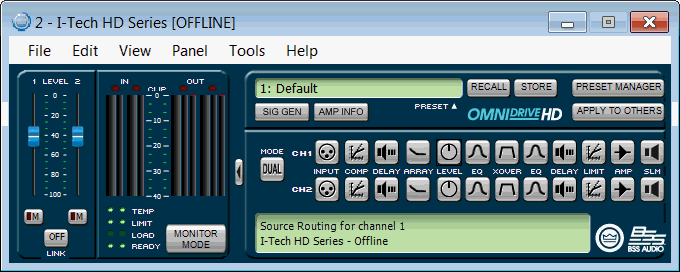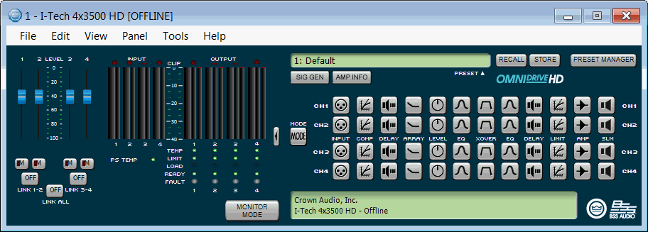


The Normal Factory Panel provides the same information as the Basic Factory Panel as a base level of functionality. From there additional features will be available. There will be three different views for the Normal Factory panel depending on the amplifier configuration. The icons indicate if that processing block is active by changing color to blue; some items will not have an active state. All processing blocks can be drag copied as well as be copied by single clicking and giving that processing block focus.
The level controls have a displayed range of -100dB to 0dB. These controls, which are a vertical fader, are connected to the appropriate Channel Output Attenuator Fader. There is an annotated scale for showing the range or control.
The Channel Output Mute control is attached to latching On/Off buttons with a dim or dark red indicator when the channel is unmuted and bright red when it is muted.
The Input Level Meters are attached to the Channel Input Router Level Meter. It is actually composed of two meters which show the Peak and the RMS level for that signal. The two indicators will be green in color, but not the same color. There is an annotated scale for showing the level range, which will run 0 to -40dBFS.
Placed above the Input Meters are Input Clip indicators. These LED indicators turn red while a clip event is taking place.
The Output Level Meters also show both Peak and RMS level for the output. These meters are connected to the Amp Output Voltage level and will be blue, but not the same color. There is an annotated scale for showing the level range, which will run 0 to -40dBFS
Placed above the Output Meters will be Output Clip indicators. These LED indicators will turn red while a clip event is taking place.
There are LED indicators for the amplifier status. The four indicators, from top to bottom, for each channel are:
The indicator will display green if the amount of thermal headroom used is less than or equal to 60%, yellow is between 60% and 80%, and red if greater than or equal to 80%.
The LED indicator turns yellow anytime gain reduction is greater than 0 and less than 20dB throughout the signal path. It will turn red when the gain reduction is greater than 20dB.
The Load Status indicator will display one of three colors. The indicator will display green if the Load Status is within the defined range, yellow if the load is below the lower threshold, and red if the load is higher than the upper threshold.
The LED indicator will illuminate green when the amplifier channel is enabled and ready to pass audio. It does not indicate if the amplifier is muted.
There is a link button to link the two Input Faders together; this will not affect the mute states. These two faders will retain their relative offset. There is also an indication on the control as to whether or not the two faders are linked together.
There is a graphic that indicates that the panel can be shrunk to the Basic View. Clicking this button will change the panel view to Normal View.
Clicking the Preset Recall button launches the Preset Recall function. Please refer to the Presets section for more information.
When a parameter value has changed in a preset, the store button will turn yellow on the main control panel. Clicking the Preset Store button launches the Preset Store function. Please refer to the Presets section for more information.
Clicking the Preset Manager button launches the Preset Manager dialog box. Please refer to the Preset Manager section for more information.
Clicking the Amp Info button launches the Amplifier Information page. Please refer to the Amplifier Information section for more information.
Clicking the Sign Gen Button opens the Signal Generator panel. Please refer to the Signal Generator section for more information.
Clicking the Apply to Others button opens the Apply to Others panel. Please refer to the Apply to Others section for more information.
Double clicking the Amplifier Mode button opens a modal dialog box for setting the input mode of the amplifier. For more detail, please refer to the Amplifier Mode section for more information.
Double clicking the Input Configuration icon for each channel opens the corresponding channel’s Source Routing Panel. Please refer to the Source Routing section for more information.
Double clicking the Input Compressor icon for each channel opens the corresponding channel’s Input Compressor. Please refer to the Input Compressor section for more information.
Double clicking the Input Delay icon for each channel opens the corresponding channel’s Input Delay. Please refer to the Input Delay section for more information.

Double clicking the Array Size Compensation icon for each channel opens the channel's Array Size Compensation filter.

Double clicking the Array Gain icon opens a window with a level control slider for that channel's array.
Double clicking the Input EQ button for each channel opens the corresponding channel’s Input EQ Filters. Please refer to the Input EQ section for more information.
Double clicking the Crossover button will open the Crossover panel. As the cross over function can vary depending on what mode the amplifier is configured for, this button can either be on a single icon spanning both channels or two icons. Please refer to the Crossover section for more information.
Double clicking the Output EQ button for each channel opens the corresponding channel’s Output EQ Filters. Please refer to the Output EQ section for more information.
Double clicking the Driver Delay button for each channel opens the corresponding channel’s Output Filter. Please refer to the Driver Delay section for more information.
Double clicking the Output Limiter button for each channel opens the corresponding channel’s LevelMAX™ controls. Please refer to the LevelMAX section for more information.
Double clicking the Amplifier Controls button for each channel opens the corresponding channel’s amplifier monitoring options. Please refer to the Amplifier Settings section for more information.
Double clicking the Sweep Load Monitoring button for the amplifier opens the Sweep Load Monitoring panel. There is one Sweep Load Monitoring for the entire amplifier. Please refer to the Sweep Load Monitoring section for more information.
The Active Help section of the Normal Factory Panel will indicate what you are hovering over. Double clicking the Active Help section will launch the help file for the amplifier.
If you are connected to the Internet you can find a video overview of
this feature at:
http://www.crownaudio.com/tutorials/