Room Combine
Today, most hotels and conference facilities rely on flexible room configurations
for a wide variety of events. Typically this involves one or more large
rooms that may be divided by flexible partitions. These combinations of
space are referred to as “room combining” and have their own unique requirements
when it comes to the audio system. The key is the management of the audio
signal to interconnect sub-room sound systems when those sub-rooms are
combined into larger rooms.
There must be at least two rooms in order to use the Room Combine function.
It is assumed here that rooms have been created. To begin, see Define the Venue.
Combining
Rooms
Creating
Partitions
Add Room Combine
Processing Object
Room
Combine Properties
Room
Combine Panel
Partition
Mode
To begin combining rooms, select the Define Venue tab.
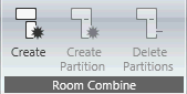 Select the rooms you wish to combine and click the
Create button in the Room Combine section of the ribbon. This will add
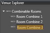
a Room Combine group in the Venue Explorer. Enter a name for the Room
Combine group. Shown below are three groups. In addition, the right-click
menu option has a rename function as well.
Select the rooms you wish to combine and click the
Create button in the Room Combine section of the ribbon. This will add
a Room Combine group in the Venue Explorer. Enter a name for the Room
Combine group. Shown below are three groups. In addition, the right-click
menu option has a rename function as well.
To add a partition between rooms, select the two rooms and click the
Create Partition button. Shown below is a partition between Salon A and
Salon B which together are the Blue Room. Partitions may be selected and
re-sized.

Select Add Devices in the Workflow section of the Offline Ribbon and
add the BSS BLU device that will be configured with the Room Combine function.
Open the BLU device and select Processing Objects at the bottom of the
Venue Explorer. To add a Room Combine group, first select Venue Explorer
at the bottom of the Venue Explorer window, then click and drag one of
the groups on the left to the BLU device configuration area on the right
as shown below:

The Room Combine Output Order/Priority window will appear:
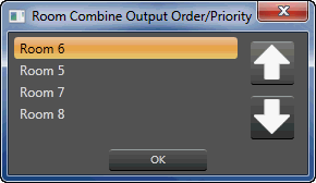
Select rooms you wish to have moved up or down This will order
the rooms from top to bottom in the Room Combine processing object. Note
above the rooms outputs are ordered Room 6 at the top, then Room 5, Room
7 and Room 8 at the bottom. Clicking OK brings up the Room Combine processing
object.
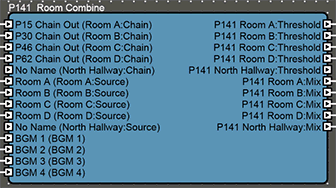
Room Combine processing object
The Room Combine processing object simplifies system setup for such
a 'room combining' application. When rooms are "combined", all
controls for each involved room will mirror each other perfectly. These
controls are objects like faders, mute buttons and source selectors.
Note that the Room Combine outputs are ordered as directed in the Room
Combine Output Order/Priority window.
Input and Outputs
Chain/Threshold Signal Routing
The Room Combine can route client automixer control and audio signals.
When two or more rooms are involved all automixers will perform as one
single automixer to ensure proper gain levels and channel weighting are
achieved. These signals are the Chain and Threshold signals located on
Client automixers. Host Automixers or Standalone automixers cannot be
used in conjunction with the Room Combine for proper operation. Client
Automixers do not have a Host gain control. When using the Client Automixer
in conjunction with the Room Combine P.O., the Host gain fader is the
"Mix" fader located inside The Room Combine P.O.

Room Source: The Room Source
inputs are for receiving a mono audio output from each room. The Source
signal input needs to be connected to the output signal of the Client Automixer
if Automixers are utilized.
Background Music (BGM): The
BGM input is used for receiving audio to be distributed in each room as
background music. When two or more rooms are combined, the combined rooms
will receive the same BGM source.
Room Mix: This output from the
P.O. has the mixed audio signal for each room, composed of the room source
audio and the BGM audio.

Signal Names: Click here to
edit the output signal names. Brings up the Signal
Naming window.
Number of Rooms: Indicates the
number of rooms in the group.
Number of Partitions: Indicates
the number of partitions in the group.
Number of BGM Inputs: Sets the
number of background music inputs.
Group Colors

The fill color share between rooms in the indicated group. Brings up
the Select Color window. This
will be the color of the border around the selected group in the Room
Combine panel when in Simulate
Venue or Run Venue modes
Options
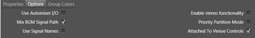
Use Automixer I/O: When checked,
the 'Chain' and 'Threshold' signals will be available for wiring with
Automixer Gain Sharing. Note
that the Automixer Gated cannot be used.
Enable stereo functionality:
Creates left and right output mixes for each room.
Mix BGM Signal Path: When checked,
the background music (BGM) signal is mixed with the room mix input.
Priority Partition Mode: When checked:
1. Room Combine will operate in 'partition'
mode where opening or closing partitions determines which group a room
will be part of.
2. When each room is created it will be assigned
a 'default group' number which is the same as the room number.
3. When rooms are combined, the group number
for the combined room will be set to the lowest numbered room which is
present in the room combination.
4. When a room is combined with an existing
group of rooms, the room controls will take on the values of the highest
priority room (i.e. lowest room number) in the group which is formed.
Example 1) Room 1 and Room 2 are combined to form a new room group (group
1). Room 1 host gain is set at 0dB, Room 2 host gain is set at -10dB.
At the instant the rooms are combined, both rooms host gain will be
set to 0dB.
Example 2) Room 1 and Room 2 are already combined in a room group (group
1). Room 3 is combined into the group. Room 1 and 2 host gains are set
at 0dB, Room 3 host gain is set at -20dB. At the instant the rooms are
combined, all rooms host gains will be set to 0dB.
This mode can be useful when you need to perform some logic which is
dependent upon knowing the current group that a room is in, e.g. disable
the room controls when a room is combined with a higher priority 'host'
room. From the design tree you can drag and drop the group (for the room
you are checking) onto a logic comparator. Then assign the compare value
to be the group number you wish to test against. The logic comparator
can then be wired to other objects such as presets, logic ends and so
on which can be used to trigger other processing objects or actions. The
example shown below can be read as "when room 2 is combined with
room 1, i.e. when room 2 becomes part of group 1, do this particular action",
and "when room 2 is not combined with room 1, i.e. when room 2 is
part of group 2, do this (other) action
When Priority Partition Mode is
unchecked:
1. Room Combine may operate in 'room' mode
or in 'Partition' mode. In 'room' mode rooms are selected to join a particular
group.
2. Each room is created with a default group
of 0 ('unassigned').
3. When rooms are combined, the next available
group (in sequence 1..number of groups) will be used to determine the
group for the room combination.
4. When a room is combined with an existing
group of rooms, the room controls for the room group formed will take
on the most conservative values of all the rooms in the group which is
formed.
Example 1) Room 1 and Room 2 are combined to form a new room group (group
1). Room 1 host gain is set at 0dB, Room 2 host gain is set at -10dB.
At the instant the rooms are combined, both rooms host gain will be
set to -10dB.
Example 2) Room 1 and Room 2 are already combined in a room group (group
1). Room 3 is combined into the group. Room 1 and 2 host gains are set
at 0dB, Room 3 host gain is set at -20dB. At the instant the rooms are
combined, all rooms host gainswill be set to -20dB.
Changing any of the above properties will cause the default control
panel to close.
Use Signal Names: When checked,
the BGM selectors will use the signal names.
Attached to Venue Controls:
When checked (default), the Room Combine processing object can be controlled
by actions in Room Combine mode. When unchecked, Room combine controls
are unattached.
This doesn't change the functionality of the Room combine processing
object... it only changes how it can be used in room combine mode.
This function is used to turn off Room combine functionality, to create
a custom User Interface with custom control panels.
Note: this is an advanced
feature. Use only if custom panels are to be created from Room Combine
control.
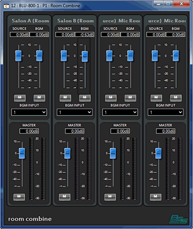 Source Fader: A fader is provided
to control the level for each Source input.
Source Fader: A fader is provided
to control the level for each Source input.
Source Mute: A mute control
is provided for each of the Source inputs.
BGM Fader: This fader controls
the level of the background music being fed into each room. This will
not be displayed if the number of BGM inputs is set to 0.
BGM Mute: Used to mute or unmute
the background music being fed into each room. This will not be displayed
if the number of BGM inputs is set to 0.
BGM Input: Use this source select
to chose which BGM source is being fed into the room. This will not be
displayed if the number of BGM inputs is set to 0.
Host Fader: This fader controls
the mix of the source input and the BGM input.
Host Meter: This meter represents
the audio which is being fed into the room. If the 'Enable Stereo' property
is set to 'Yes' then separate meters for both left and right stereo channels
will be displayed.
Host Mute:This mute controls
the mute-state of all sources being fed into this room
The Room Combine panel shows mute and level controls for each Source
and BGM input. The BGM Input window is for selecting which BGM Input source
will be used for that room. Each room has a Host level and mute control.
This panel may be converted
to custom the same as other Audio Architect panels for use in a custom control panel.
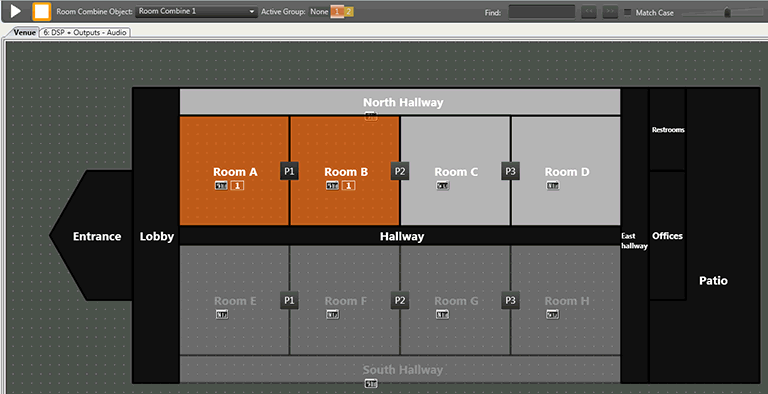
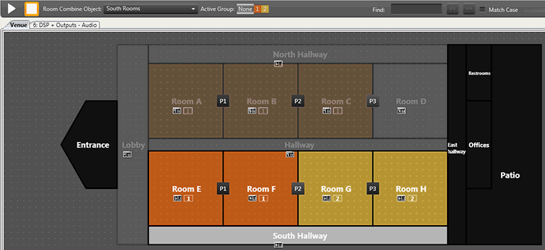
In Simulate Venue or Run Venue mode, the borders around a room group
will match the color of a selected room group.
 Active group: None selected
 Active group: 1 selected

With Active group 1 selected, selecting Rooms 1 and 4 will highlight
Rooms 1 and 4 on the Room Combine panel. The same action applies for selecting
Active Group 3, then selecting Rooms 2 and 5.

Note on the Room Combine panel, the Active Group color corresponds with
the selected Room.
Partition mode is where rooms are combined according to the current
state of a 'wall partition' connecting the two rooms. In a real situation
the wall partition state could be driven from a relay contact coming into
the Soundweb London unit as a control port input.
Opening a Wall Partition
The wall partition
between rooms 1 and 2 is opened
Room 2 joins
room 1's group as it is has lower group number
The rooms become
the same color to show the rooms are in the same group
All controls
for room 1 and 2 are linked together in an exact link
Closing a Wall Partition
The wall partition between rooms 1 and 2 is closed
Rooms 1 and
2 are set to no specific group (None / 0)
Rooms 1 and
2 become gray to show the rooms are not part of any group
All controls
for rooms 1 and 2 are unlinked

Opening a wall partition
between groups
The wall partition
between two existing groups is opened
The rooms which
are in the higher numbered group are set to be in the lower numbered
group
The rooms colors
change appropriately showing the rooms in the new group
The controls
for all rooms in the new group are linked
Closing a wall partition
between groups
Closing a wall
partition splits a group
The room colors
change appropriately
Controls are
unlinked between the rooms and linked according to their new sub-groups
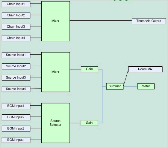
Room Combine DSP Primitives
This section illustrates the use of DSP primitives by the Room Combine
processing object as an aid to understand how it works internally. The
example below shows the processing which is required 'per room' for the
following setup :
If separate BGM and room source outputs were required, i.e. 'Mix BGM
Signal Path' property = 'No' then the DSP primitives would look like :
 Notes:The two gains work
like a 2 input 'n-input' gain. The actual gain applied is the gain for
the source or BGM, PLUS the host gain.
Notes:The two gains work
like a 2 input 'n-input' gain. The actual gain applied is the gain for
the source or BGM, PLUS the host gain.
The summer is a simple mixer that applies unity gain